Visual Effects
Aim - this section provides an overview of the typical operation of special visual effects, which could include steam or smoke on the steam locomotive and wagons, and describes how to define these effects in Open Rails (OR)
If you wish to provide any feedback on this page, please use the contact page. It would be great to have some feedback as this helps to ensure the accuracy of the information and models.
Index
Overview of Key Visual Effects
Visual Effects Code - Structure and layout in Open Rails
Effects Parameters Co-ordinates Description
Code Segments for Various Visual Effects Examples
Overview of Key Visual Effects
Steam Locomotives
The ancillary devices on a steam locomotive, such as the air compressor and water injectors are typically powered by steam from the boiler. Steam for these devices is piped around the locomotive. Thus, a steam locomotive can have steam exhausting from it at various locations. Using a NSWGR P Class (C32) locomotive as an example the principal steam powered devices are shown in the diagram below, and their basic operation described.

- Stack - smoke from the combustion of the fuel (coal, wood, etc.) was exhausted out of the smoke stack. Steam exhaust from the steam cylinders was exhausted out of the stack as well, which created additional draught for the fire, and sometimes gave the smoke emission a "puffing" appearance.
- Steam cylinder cocks - steam could condense in the steam cylinders to become water. Water in the steam cylinders could severely damage the cylinders when they were in operation, so cocks were placed in the steam cylinders which the locomotive driver could open and blow water condensation out of the steam cylinders. Typically, the steam cocks were located at either end of the steam cylinders and were operated just prior to moving the train, or as the train started to move.
- Air compressor - to provide the necessary air supply for the Westinghouse air brake system an air compressor was fitted to the locomotive. Typically, the exhaust steam from running the air compressor was exhausted into the smoke box of the locomotive.
- Turbo-generator - On some locomotives electric marker and headlights were installed, and this required a small electric generator to be fitted. This generator was driven by a turbine with the steam exhausting directly to the atmosphere.
- Whistle - steam whistles were mostly fitted to steam locomotives with steam used to operate them being exhausted to the atmosphere.
- Safety valves - were fitted as a safety feature to reduce the boiler pressure if it became excessive. The safety valves were designed to open at slightly higher pressures then the maximum boiler pressure, and by exhausting the steam to the atmosphere excess heat was removed from the boiler, which in turn reduced the boiler pressure.
- Water injector - On most locomotives steam powered water injectors were used to push water from the tender into the boiler of the locomotive. Most of the steam was mixed with the water and ended in the boiler, however a small amount was exhausted out of a drain pipe near the injector. Typically, two injectors either side of the locomotive were fitted.
- Boiler Blowdown Valve - A boiler blowdown valve was fitted to allow the driver to drain sediments out of the boiler. Allowing sediments to remain in the boiler could result in a drop in boiler efficiency.
- Track Steam Sanding System - on some locomotives steam was used to propel the sand onto the tracks.
The actual locations of the actual steam effects may vary slightly from locomotive to locomotive.
Wagons
Special visual effects, such as steam and smoke can be also added to wagons. This might included simulated steam leaks between cars on a train that has steam heating, exhaust smoke from auxiliary generators or diesel boilers and wood fires in guards vans.
Visual Effects Code - Structure and layout in Open Rails
Steam Locomotives
Steam exhausts on a steam locomotive can be modelled in OR by defining appropriate steam effects in the
OR supports the following special steam effects on steam locomotives:
- Stack (named
StackFX ) - represents the smoke stack emissions. This effect will appear all the time in different forms depending upon the firing and steaming conditions of the locomotive. - Stack - Engine #1 or default - (named
CylinderSteamExhaust1FX ,CylinderSteamExhaust2FX ,CylinderSteamExhaust3FX ,CylinderSteamExhaust4FX ) - represents the steam exhausted out of the stack (which gives the steam locomotive its "puffing" appearance. There is one effect for each steam cylinder, and the exhaust is timed to the cylinders operation. - Stack - Engine #2 - (named
CylinderSteamExhaust2_1FX ,CylinderSteamExhaust2_2FX ,CylinderSteamExhaust3FX ,CylinderSteamExhaust4FX ) - represents the steam exhausted out of the stack (which gives the steam locomotive its "puffing" appearance. There is one effect for each steam cylinder (assumed that second engine only has two cylinders), and the exhaust is timed to the cylinders operation. - Stack - Booster Engine - (named
BoosterCylinderSteamExhaust01FX ,BoosterCylinderSteamExhaust02FX - represents the steam exhausted out of the stack (which gives the steam locomotive its "puffing" appearance. There is one effect for each steam cylinder (assumed that the booster engine only has two cylinders), and the exhaust is timed to the cylinders operation. - Steam cylinder Cocks - Engine #1 or default - (named
Cylinders11FX andCylinders12FX ,Cylinders21FX andCylinders22FX ,Cylinders31FX andCylinders32FX ,Cylinders41FX andCylinders42FX ), where CylindersyzFX, y = cylinder number, and z = exhaust point- two effects are provided for each cylinder which will represent the steam exhausted when the steam cylinder cocks are opened. The effects are provided to represent the steam exhausted at the front and rear of each piston stroke. These effects will appear whenever the cylinder cocks are opened, and there is sufficient steam pressure at the cylinder to cause the steam to exhaust, ie, when the regulator is open (> 0%). - Steam cylinder Cocks - Engine #2 - (named
Cylinders2_11FX andCylinders2_12FX ,Cylinders2_21FX andCylinders2_22FX , where Cylindersx_yzFX, x = engine number, y = cylinder number, and z = exhaust point - two effects are provided for each cylinder which will represent the steam exhausted when the steam cylinder cocks are opened. The effects are provided to represent the steam exhausted at the front and rear of each piston stroke. These effects will appear whenever the cylinder cocks are opened, and there is sufficient steam pressure at the cylinder to cause the steam to exhaust, ie, when the regulator is open (> 0%). - Booster cylinder Cocks - Engine #1 or default - (named
BoosterCylinders11FX andBoosterCylinders12FX ,BoosterCylinders21FX andBoosterCylinders22FX , where BoosterCylindersyzFX, y = cylinder number, and z = exhaust point- two effects are provided for each cylinder which will represent the steam exhausted when the steam cylinder cocks are opened. The effects are provided to represent the steam exhausted at the front and rear of each piston stroke. These effects will appear whenever the cylinder cocks are opened, and there is sufficient steam pressure at the cylinder to cause the steam to exhaust, ie, when the regulator is open (> 0%). - Air compressor (named
CompressorFX ) - represents a steam leak from the air compressor. Will only appear when the compressor is operating. - Turbo-generator (named
GeneratorFX ) - represents the emission from the turbo-generator of the locomotive. This effect operates continually. If a turbo-generator is not fitted to the locomotive it is recommended that this effect is left out of the effects section which will ensure that it is not displayed in OR. - Whistle (named
WhistleFX ) - represents the steam discharge from the whistle. - Safety valves (named
SafetyValvesFX ) - represents the discharge of the steam valves if the maximum boiler pressure is exceeded. It will appear whenever the safety valve operates. - Water injectors (named
Injectors1FX andInjectors2FX ) - represents the steam discharge from the steam overflow pipe of the injectors. They will appear whenever the respective injectors operate. Injector 1 is normally operated by the Fireman and is the main Injector in use. - Steam ejectors (named
SmallEjectorFX andLargeEjectorFX ) - represents the steam discharge from the steam ejectors associated with vacuum braking. They will appear whenever the respective ejectors operate. - Boiler blowdown valve (named
BlowdownFX ) - represents the steam discharge from the boiler when the blowdown valve is opened. - Tracke Sanding System - typically for steam locomotives (named
SanderSteamExhaustForwardFX and/orSanderSteamExhaustReverseFX ) - represents the steam discharged from the sanding system when sanding is turned on.
NB: If a steam effect is not defined in the
The typical structure of the visual effects section for a steam
Effects (
SteamSpecialEffects (
Effect Name (
Effect location
Effect direction
Effect nozzle width
)
)
)
Note: It is important to ensure that the opening and closing brackets for the effects section match up, otherwise errors maybe generated.
Diesel Locomotives
Various exhaust effects on a diesel locomotive can be modelled in OR by defining appropriate effects in the
OR supports the following special visual effects on diesel locomotives:
- Exhaust (named
Exhaust number) - is a diesel exhaust. Multiple exhausts can be defined, simply by adjusting the numerical value of the number after the key word exhaust.
NB: If a visual effect is not defined in the
The typical structure of the visual effects section for a diesel
Effects (
DieselSpecialEffects (
Effect Name (
Effect location
Effect direction
Effect nozzle width
)
)
)
Note: It is important to ensure that the opening and closing brackets for the effects section match up, otherwise errors maybe generated.
Wagons
Various exhausts on a wagon can be modelled in OR by defining appropriate visual effects in the
OR supports the following special visual effects on wagons:
- Steam Heating Boiler ( named
HeatingSteamBoilerFX ) - represents the exhaust for a steam heating boiler. Typically this will be set up on a diesel or electric train as steam heating was provided directly from a steam locomotive. - Wagon Generator ( named
WagonGeneratorFX ) - represents the exhaust for a generator. This generator was used to provide additional auxiliary power for the train, and could have been used for air conditioning, heating lighting, etc. Currently operates continuously. - Wagon Smoke ( named
WagonSmokeFX ) - represents the smoke coming from say a wood fire. This might have been a heating unit located in the guards van of the train. Currently operates continuously. - Heating Hose ( named
HeatingHoseFX ) - represents the steam escaping from a steam pipe connection between wagons. By convention, it is suggested that this steam effect only be position on the start of each wagon. If it is placed on the rear of the wagon then the last car will have a steam leak which is probably not as realistic. Only operates when steam heating is operational on the train. - Water Scoop ( named
WaterScoopFX ) - represents the water thrown up as the water scoop moves along the water trouygh or pan. By convention, it is suggested that this effect be positioned either side of the water scoop on each wagon. Only operates while the water scoop is in the down position, and train is on the water trough (currently only available in MG version). - Tender Water Overflow ( named
TenderWaterOverflowFX ) - represents the water overflowing out of the tender or water tank when it is full, and the water scoop is left in the down position (currently only available in MG version).Only operates when water tank is full and scoop is left in down position. - Bearing Hotbox ( named
BearingHotboxFX ) - represents the smoke generated in the bearing if it overheats (currently only available in MG version). Only operates whilst bearing temperature is above the warm temperature. - Steam Brake Leaks ( named
SteamBrakeFX ) - represents the steam leaks associated with the operation of the steam brake. Turns on and off with the steam brake..
NB: If a visual effect is not defined in the
Note: Any of the wagon effects can be added to either a steam or diesel locomotive by adding the relevant visual effects into the wagon section of the respective
The typical structure of the visual effects section for a wagon
Effects (
SpecialEffects (
Effect Name (
Effect location
Effect direction
Effect nozzle width
)
)
)
Note: It is important to ensure that the opening and closing brackets for the effects section match up, otherwise errors maybe generated.
Effects Parameters Co-ordinates Description
Within each individual steam effect the following information is defined:
- Effect name - name defining which effect is defined (see above text for a list of the names).
- Effect location - location on the locomotive (given as an x, y, z offset in metres from the origin of the wagon shape).
- Effect direction - direction of emission (given as a normal x, y and z).
- Effect nozzle width - size of the exhaust nozzle in metres.
Location - Typically the origin point is in the centre of the locomotive, with the x, y and z axis describing a location referenced to this point. When looking to the front of the locomotive from the cab:
- X axis - to the right (+ve), or left (-ve)
- Y axis - in up (+ve) or down (-ve) direction.
- Z axis - to the front (+ve) or back (-ve) of the origin.
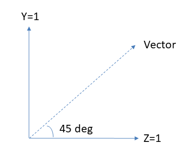
Direction - The direction of the effect (vector) is defined with the x, y and z axes using the same convention as the location stated above.
In most cases the effect is only required to show in one direction along the x, y or z axes. This is simple to define as in the following manner,
- X axis - to the right (+ve), or left (-ve)
- Y axis - in up (+ve) or down (-ve) direction.
- Z axis - to the front (+ve) or back (-ve) of the origin.
Any number greater or less than zero can be used for the single direction flow but it is obviously more convenient to use 1 or -1.
Angles can be created by visualising the diagram below, and allocating appropriate numbers to the y and z axes. A 45 deg. angle vector would have two of the axes with either a 1 or -1 value depending upon the direction required.
A shallower 20 deg. angle can be created as below.

The Y axis has been determined by using tan theta. Tan (20 deg) = 0.364, where Z is assumed the principle axis and designated a value of 1.
Y could have been chosen as the principle axis. In this case Y=1 and Z=tan(90-theta) = tan (70 deg) = 2.7474. This will produce exactly the same effect.
The third dimension X may also be introduced if required and calculated in a similar manner as above.
Calculate Effect Angle
Using the above convention of a Principal and Secondary Axis the following calculator will calculate the value required for the secondary axis. It is assumed that the Principal axis is set at a value of 1, and the angle between the principal axis and the desired direction is entered into the calculator.
Code Segments for Various Visual Effects Examples
Note: It is good practice to put notes into the
Comment ( Injector - Left )
The steam effect examples on this page represents use of the steam configuration parameters described above to define different types of steam effects.
This type of code goes into the
Typically the lines shown in red text are the only ones that would need to be changed to suit individual locomotives.
![]() To locate an effect, use the "MSTS Positioning Tool" in Shape Viewer to correctly define the location of the steam effect. Just open the positioning tool as a second shape, move it to the position you want the new view/effect/light, and read the coordinates off the "Position Second Shape" window. Copy the values determined by Positioning Tool into the location and direction fields of the parameters in the
To locate an effect, use the "MSTS Positioning Tool" in Shape Viewer to correctly define the location of the steam effect. Just open the positioning tool as a second shape, move it to the position you want the new view/effect/light, and read the coordinates off the "Position Second Shape" window. Copy the values determined by Positioning Tool into the location and direction fields of the parameters in the
Steam cylinder cock
This is a example of how the steam cylinder cocks can be set up. Note that there are two different effects representing the two ends of the piston stroke. It is suggested that these are "reversed" on the opposite sides of the locomotive.
Comment ( Cylinder - Left/Rear )
Cylinders11FX (
-1.0485 1.0 2.8
-1 0 0
0.1
)
Comment ( Cylinder - Left/Front )
Cylinders12FX (
-1.0485 1.0 3.7
-1 0 0
0.1
)
Comment ( Cylinder - Right/Rear )
Cylinders21FX (
1.0485 1.0 2.8
1 0 0
0.1
)
Comment ( Cylinder - Right/Front )
Cylinders22FX (
1.0485 1.0 3.7
1 0 0
0.1
)
Air compressor
This is a example of how the air compressor(s) can be set up. Note that in this instance there are two compressors on the locomotive, so the same effect can be used twice at different locations to model this effect.
Comment ( Compressor - Back )
CompressorFX (
-1.15 2.65 -1.75
-1 -1 0
0.05
)
Comment ( Compressor - Front )
CompressorFX (
-1.15 2.65 -1.15
-1 -1 0
0.05
)
Working excamples demonstrating the above concepts have been built into some of the stock on the stock page.