OR Steam Locomotive Model
Aim - This page aims to describe how the steam locomotive has been modeled within Open Rails.
If you wish to provide any feedback on this page, please use the contact page. It would be great to have some feedback as this helps to ensure the accuracy of the information and models.
Index
Cylinder Mean Effective Pressure
Motive Force (Tractive Effort)
Advanced Performance Tuning Flowchart
Introduction
Steam locomotives are in effect complex heat engines, and by virtue of this, their performance and design was very much an empirical (experimental) process. For example, a locomotive would be built, and then tested to see how it performed. Good features on the locomotive were often then incorporated into future new locomotive designs, sometimes successfully, sometimes not. A series of design formula were defined based upon the test results, and these were used as a starting point for future designs, however the performanace of a locomotive was never truely certain until it was tested.
Due to the empirical nature of steam locomotive design, and the variety of locomotives built over the years, it is very difficult to find detailed test reports, and in fact, any detailed information accurately specifying the locomotive performance. The lack of well defined formulas for most features has also created challenges in developing the model. Thus the OR steam model, has adopted a generic approach, and therefore whilst the model provides a reasonable representation of the different types of steam locomotive, some variations from 'reality' may be noticed. A number of test reports have been collected from different sources, and these have been used to validate the authenticity of the model as much as possible.
The steam model has been developed based upon the following desired outcomes:
- Ease of Definition -
ENG files can be created quickly and easily using standard information about the locomotive, which ideally should be readily available from the Internet. Some tuning parameters have been added to allow interested modellers to tune a locomotive based upon detailed test reports if available - Performance - should be able to maintain prototypical timetables under relevant operating conditions which will include route gradients, loads, etc.
It is recommended that the section on Steam Train Physics is read in conjunction with the description of the OR steam model below.
The following sections provide a brief description of the OR steam model which has been used within Open Rails to simulate the operation of a steam locomotive. It is important to have a reasonable knowledge of the Steam model, and how changing different parameters will impact locomotive performance.
Detailed Train Operation Information
Open Rails provides detailed information showing the operation of steam locomotives. This information is available in the Extended HUD, which can be accessed by pressing the
Plotting of Key Performance Measures
To monitor the performance of the steam locomotive a number of key operational measurements are able to be plotted onto a graph at 5mph intervals. The resultant graphs allow comparison with relevant test data or curves. To use this tool:
- OR Setup - OR needs to be configured to record (log) values into the
Dump.csv at 5mph intervals. TheDump.csv file can normally be found on the computer Desktop. To set up logging go into the 'Data Logging' TAB in the Options menu, and tick the following boxes: 'Log Steam Performance data' and Start logging with the simulation start'. Ideally other loging options should be off. It is also recommended that theDump.csv is deleted before each run so that only the data for the most recent run is present. - Spreadsheet - A special test spreadsheet template has been set up to allow graphing of the measurements, and can be downloaded. The relevant data can then be copy and pasted from the
Dump.csv file into the downloaded test.
The following test template spreadsheets have been developed to allow monitoring of key performance measures in OR. Two versions of the spreadsheet have been developed. One is more suitable for plotting British test report results, and the other is more suitable for plotting American test report results. The use of this tool requires either Microsoft Office or Open Office programs.
![]() American Format - Test Results Excel Spreadsheet - v6 (Compatible with OR #3848 and later)
American Format - Test Results Excel Spreadsheet - v6 (Compatible with OR #3848 and later)
![]() British Format - Test Results Excel Spreadsheet - v6 (Compatible with OR #3848 and later)
British Format - Test Results Excel Spreadsheet - v6 (Compatible with OR #3848 and later)
To use the above spreadsheets
- Run a test in OR (once logging has been enabled)
- Open the relevant test template spreadsheet, and the
Dump.csv file as an Excel file - Select all the data in the
Dump.csv file from column 2 onwards, and below row 1 (heading), and then copy and paste this block into the corresponding position in the relevant test template spreadsheet
Overview of Steam Model
The following diagram and accompanying description provides an overview of the OR steam model, individual modules will be described in more detail within the sections below.
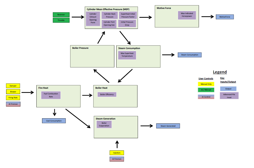
The steam model consists of a number of interconnected program modules which calculate the key elements of the steam locomotive. The principal output of the steam model is the 'MotiveForce' (or in reality the Tractive Force). This force is passed to other modules within OR which use it to calculate whether there is sufficient force available to move the train, and the speed of operation etc. ( Principles for Steam Train Movement ). The other key element of the model is the boiler pressure, which impacts directly upon the MotiveForce. The boiler pressure is in turn directly impacted by the boiler heat, ie decreasing 'real time' boiler heat will reduce the boiler pressure, whilst increasing boiler heat will increase the boiler pressure.
A brief description of each module shown in the overview diagram is provided here, but a more detailed description will be provided in the sections below.
- Cylinder Mean Effective Pressure (MEP) - calculates the mean effective pressure (MEP) in the cylinder. MEP is calculated by modelling a 'typical' Indicator Diagram for the type of locomotive being modelled. The MEP is impacted by the boiler pressure, and the settings applied by the driver through the throttle and reverser. The MEP is used to calculate the MotiveForce, and steam usage, etc.
- MotiveForce - this module uses the MEP to calculate the 'MotiveForce' (Tractive Force) of the locomotive.
- Steam Usage - this module calculates the various steam usages in the locomotive. The principal one being the cylinder steam usage which feeds into the Boiler Heat module, and reduces the heat in the boiler.
- Boiler Pressure - this module calculates the boiler pressure based upon the aggregate boiler temperature. Reducing boiler pressure will reduce the MEP, and thus the MotiveForce.
- Boiler Heat - this module calculates the 'real time' heat in the boiler by summing the heat provided by the fire, and heat lost through steam usage, and the introduction of injector water, etc. The Boiler Heat will impact the real time boiler pressure.
- Steam Generation - this module calculates the steam produced by the burning of the fuel.
- Fire Heat - this module calculates the heat produced by the burning of the fuel. It is an input to the Boiler Heat module to overcome any heat losses, such as through the usage of steam in the cylinders.
This diagram shows the ADVANCED performance tuning inputs (purple boxes) available in the model. Typically it is expected that only interested users will wish to explore these further. The basic parameters should provide a realistic performance for the locomotive.
Cylinder Mean Effective Pressure
The mean effective pressure is mean value of the pressure applied within the cylinder and provides a measure of the work done in the cylinder by the steam. This work is translated into a tractive force, which in turn is applied to the wheels of the locomotive to move the train. The pressure in the cylinder also impacts the quantity of steam used by the locomotive.
The following diagram and accompanying text describes the key elements of the Clylinder Mean Effective Pressure calculation module within the OR Steam model.

Several pressure drops occur during the journey of the steam to the cylinder from the boiler, and these impact the final value of the MEP:
- Drop between boiler and cylinder steam chest - speed dependent
- Drop going through steam chest port into steam cylinder - speed dependent (also called "wire-drawing", and is caused by opening and closing of the valves).
- Cylinder condensation - causes both a pressure drop as well as increased steam usage rate.
The MEP module calculates the pressure in the steam cylinder for various cutoffs, throttle settings, and speed. Typically for real locomotives the MEP was calculated by graphing the action of the steam cylinder with an indicator diagram. Different types of locomotives will produce different types of indicator diagrams. For example, note the difference between a simple locomotive Indicator Diagram and a compound locomotive Indicator Diagram. As described in these sections, the MEP will change based upon a number of factors, including changing boiler pressure, steam path restrictions (size of steam openings, etc), and locomotive speed, which also impacts the ability of the cylinder to exahaust steam from the cylinder in a timely manner.
Inputs to this OR module include the player controls (shown as dark green boxes) for throttle and reverser (cutoff), basic locomotive design parameters such as cylinder sizes (shown as light green boxes), the current boiler pressure and speed which is calculated by OR.
The module provides outputs to other modules within OR to facilitate the calculation of MotiveForce and steam usage.
Typically the Advanced setting parameters (shown as purple boxes) have the following effect on the MEP calculation:
- Initial Pressure -
ORTSCylinderInitialPressureDrop( x y ) adjusts the Initial Pressure (point a on the indicator diagram) into the Steam Cylinder depending upon the speed of the locomotive. Many factors in the steam circuit feeding to the cylinder will impact this value. Increasing or decreasing this value will adjust the MEP value up or down respectively (and by indirect association the TE and IHP corrspondingly). - Cutoff Pressure -
ORTSCylinderPortOpening ( x ) (for Saturated locomotives) orORTSSuperheatCutoffPressureFactor ( x ) (for Superheated locomotives) adjusts the Cutroff Pressure (point b on the indicator diagram) in the Steam Cylinder depending upon the speed of the locomotive. Many factors, including the port sizes feeding into the and out of the cylinder, condensation in saturated locomotives will impact the amount of reduction or wire-drawing experienced. Increasing or decreasing this value will adjust the MEP value up or down respectively (and by indirect association the TE and IHP corrspondingly). - Back Pressure -
ORTSCylinderBackPressure( x y ) adjusts the back pressure in the cylinder. Typically increases in back pressure result in redcutions in the MEP, and hence most engineers tried to keep the Back Pressure as low as possible.
Motive Force (Tractive Effort)
Tractive Effort (or MotiveForce as it is known in OR) is calculated using the MEP, and typically the formula used for calculation of the tractive effort will vary depending upon the type of locomotive, for example simple or compound, etc.
The following diagram and accompanying text describes the Motive Force calculation module within the OR Steam model.
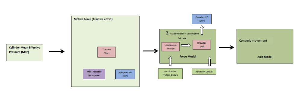
The Motive Force is used as an input by other modules within OR to calculate train movement.
For comparison with test report information, the following values are calculated by Open Rails:
- Indicated Tractive Effort - is the tractive effort (force) measured from an indicator diagram produced by the cylinder operation.
- Drawbar (or Actual) Tractive Effort - is the value measured by a dynamometer car. Typically this is the force that the locomotive is able to exert on its train, and typically is equal to the Indicated Tractive Effort - Locomotive (and Tender) resistance.
- Indicated HorsePower (IHP) - is used to try and provide a means of comparing the power of different locomotives. IHP will vary as the speed varies, so when stating the IHP ideally the speed should also be specified. Typically IHP was measured during testing of the locomotive based upon the results of indicator cards, and therefore it does not include any allowances for mechanical efficiency, so therefore does not provide a complete measure of the locomotive performance.
- Drawbar Horsepower - is measured by the use of a dynamometer car, and therefore provides an accurate measure of the actual locomotive performance. However as it excludes the work done in moving the locomotives own weight it does not provide a great deal of value.
Inputs to the module include the basic locomotive design parameters such as cylinder and wheel sizes, etc (shown as light green boxes), the current MEP pressure and speed which is calculated by OR.
Typically the Advanced setting parameters (shown as purple boxes) have the following effect on the MEP calculation:
- Maximum Indicated HorsePower -
ORTSMaxIndicatedHorsepower ( x ) - OR calculates the IHP of the locomotive at various speeds, and compares this to the MaxIHP. The power of the locomotive will be limited or reduced if the IHP exceds the MaxIHP. Increasing or decreasing this value will allow the locomotive to produce more or less power. The limit will only apply where the calculated MEP value is sufficient to develop more power then that estimated for the MaxIHP.
Steam Usage
Steam Usage is approximately equal to the volume of steam in the cylinder at cutoff exhaust pressure. The steam volume will be impacted in different ways depending upon whether the locomotive is a saturated or superheated model. A certain amount of steam will be left in the cylinder after compression, and this can be calculated by the volume space in the cylinder clearance (x2) and using a final compression pressure approx. equal to that of the initial pressure.
The following diagram and accompanying text describes the Steam usage calculation module within the OR Steam model.

Steam usage is calculated based upon the theoretical Indicator Diagram estimated for the locomotive. Typically the base steam usage is equal to the amount of steam in the cylinder at the point of cutoff pressure, minus the amount of steam that remains in the cylinder after the exhaust closes and the cylinder starts going through the compression stage. The base steam usage volume is then adjusted depending upon whether the locomotives is a Saturated or Superheated locomotive. As described in the following sections steam condensation or superheating can have a large impact upon the amount of steam used by the locomotive.
Saturated - When steam is injected into the cylinder, it comes into contact with the cylinder walls and some of the steam is condensed as water vapour. This means that extra steam is required to maintain sufficient pressure to drive the cylinder, and consequently causes higher steam consumption and fuel rates to be recorded. This will vary depending upon the cutoff value; with condensation being greater at longer values of cutoff. Typically condensation may increase steam consumption by up to 20% more, depending upon the level of cutoff.
Superheated - Superheated steam has a lot more heat energy in it then saturated steam, and consequently whilst some heat will be lost when it comes into contact with the cylinder walls, it is less likely to condense. It also has a higher volume and consequently less steam mass (lbs) is required to do the same amount of work in the cylinder. Consequently this makes the locomotive more efficient, with less steam and fuel consumption compared to a saturated locomotive. Typically superheating may reduce steam consumption by up to 40%, depending upon the level of superheating designed into the locomotive.
The steam usage module attempts to model both condensation for staurated locomotives or increased steam efficiencies for superheated locomotives. In the case of superheated locomotives, the module, calculates the superheat steam temperature based upon the size of the superheater heating area, determines the value of steam heat that is required to prevent cylinder condensation (varies with superheat temperature and cutoff), calculates current steam heat temp and steam volume increase over saturated steam, to finally reduce steam usage depending upon the steam volume increase calculated.
Cylinder Thermal Efficiency - The efficiency of the steam cylinder provides a measure of the amount of energy required (steam consumption) to produce the available power (IHP) for the locomotive. The efficiency will be different depending upon whether the locomotive is a saturated or superheated steam locomotive. For example a superheated locomotive will produce higher values of IHP (due to more work done in the cylinder) for a lower input of steam volume compared to a saturated locomotive.
Inputs to the module include the basic locomotive design parameters such as cylinder sizes, superheater heating elements, etc (shown as light green boxes), the current MEP pressure and speed which is calculated by OR.
Typically the Advanced setting parameters (shown as purple boxes) have the following effect on the MEP calculation:
- Maximum Superheat Temperature -
ORTSMaxSuperheatTemperature ( x ) (for Superheated locomotives only) adjusts the maximum superheat temperature of steam being feed into the cylinder. Increasing or decreasing this value will adjust the Steam Usage value down or up respectively.
Boiler Heat
The boiler heat module compares the heat input into the boiler generated by the fuel source against the heat ouput associated with steam usage, loss of heat due to water input, etc. The summation of the heat inputs and outputs will either be a positive number, meaning that the overall water temperature in the boiler will rise, or alternatively be negative, in which case the temperature will decrease. The resulting water temperature is then passed to the Boiler Pressure module to allow calculation of the current boiler pressure of the locomotive.
Thus, in short the boiler steam pressure is related to burning of the fuel as follows: Fire Heat => Boiler Temperature => Boiler Steam Pressure. Excessive fire heat, when there is minimal steam usage, will cause excessive boiler pressure and increase the risk of blowing off, which wastes steam. Whilst insufficient fire heat, at times of high steam usage, will cause the boiler pressure to drop to critical levels whereby the locomotive may loose power. Thus managing of the boiler heat is critical to maintaining the optimal boiler pressure.
The following diagram describes the Boiler Heat calculation module within the OR Steam model. Each of the elements in this module are described below.
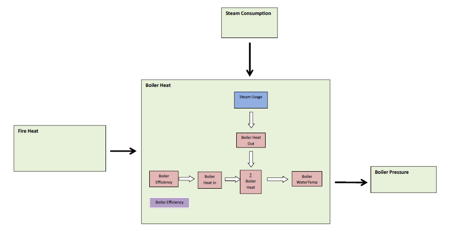
Boiler Efficiency - describes the relationship between the amount of heat inputted into the boiler(fuel burnt) versus the effective heat produced by the boiler(steam generation). Boiler efficiency depends on the design on boiler and firebox, the type of fuel, and the draughting system. In the case of coal-fired boilers, boiler efficiency declines linearly with rate of fuel feed.
Boiler Heat In is principally determined by burning of the fuel. The heat generated by the burning of the fuel is determined by the following relationship:
Boiler Heat Out is the heat lost principally due to steam usage, water replacement, and peripheral equipment such as the generator, whistle, and other steam leakages.
Steam Usage - Heat required to required to replace steam used by the cylinders and other steam devices. Calculation is based upon the assumption that the water mass heat remains the same, thus the heat 'lost' will equal the amount of heat needed to raise temp from current boiler water temp to current boiler steam heat, for the amount of steam used. Water mass heat will change when water replacement occurs. The heat lost due to steam consumption is determined by the following relationship:
Water usage - Heat required to heat replacement water coming into boiler from injectors. This will be the amount of water times the heat required to rise temp from injector water temp to boiler water temperature. The heat lost due to water usage is determined by the following relationship:
Boiler Heat Limitation - A boiler is only capable of holding a certain amount of heat; this will be determined by the volume of the boiler and the boiler operating pressure. Once this boiler heat value is exceeded, the boiler will start to exhaust steam through the safety valve in an effort to reduce the heat value. Typically the locomotive boiler works on the principle of 'heat transfer', ie heat put into the boiler is used by the cylinders straight away and therefore the boiler heat value should normally not be exceeded.
This module also generates a number of signals that are used to limit the operation of the AI fireman. For example, if the boiler heat exceeds
- Boiler Heat Ratio (BHR) - decreases burn rate if boiler heat is exceeding heat value at maximum boiler pressure
- Max Pressure Boiler Heat Ratio (MBHR) - decreases burn rate if boiler pressure if safety valve pressure is exceeded
Typically the Advanced setting parameters (shown as purple boxes) have the following effect on the MEP calculation:
- Boiler Efficiency -
ORTSBoilerEfficiency( x y ) - Boiler efficiency determines the amount of heat produced for the amount of coal burnt. Locomotives with small grate areas will be limited in terms of the amount of heat that they could produce if their boiler efficiencies were low or poor. For locomotives with small grate areas, boiler efficiency may need to be increased if the locomotive is struggling to maintain boiler pressure. Increasing or decreasing this value will allow the locomotive to produce more or less heat per grate area.
Extended HUD Interpretation
The following values displayed on the extended HUD are the key values of relevance in the Steam model in regard to the Boiler Heat module.
Displayed under
Displayed under
Fire Heat
The following diagram and accompanying text describes the Boiler Heat calculation module within the OR Steam model.
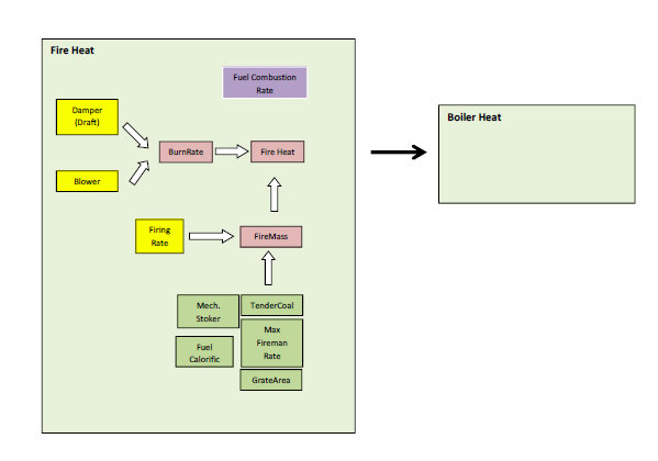
FireMass - Is dependent upon the amount of coal burnt and the coal feed rate. The firemass typically will be maintained around the ideal fire mass, which is determined by the grate area. Burning coal beyond the ability of the fireman to feed the fire will result in decreased firemass.
BurnRate - Is calculated by a curve relating steam consumption to lbs of coal burnt. BurnRate Limitation - The locomotive cannot exceed fuel firing rate indefinitely.
Grate Limit - Similarly exceeding the optimal amount of coal (thickness of layer) placed will reduce ability of fire to produce heat (modelled through the use of Boiler Efficiency)
Inputs to the module include the basic locomotive design parameters such as cylinder sizes, superheater heating elements, etc (shown as light green boxes), the current MEP pressure and speed which is calculated by OR.
Typically the Advanced setting parameters (shown as purple boxes) have the following effect on the MEP calculation:
- Burn Rate -
ORTSBurnRate( x y ) - Burn Rate determines the amount of fuel used for the amount of steam produced. Increasing or decreasing this value will result in the locomotive using more or less coal per steam used.
Boiler Pressure

Locomotive pressures - To understand the operation of a locomotive, and its capability to do work, it is useful to understand the different pressure measurements, as these represent available forces. The following pressure measurements represent the force capability available at different stages of the steam cycle.
Boiler Pressure - pressure in the boiler, and represents the maximum available pressure to be provided to the cylinders.
Steam Chest Pressure - pressure in the steam chest on the input side of the cylinders, and represents the maximum steam pressure to the cylinders. Typically this would normally be the same as the boiler pressure.
Initial Pressure - is the pressure that is actually applied to the cylinder piston and will be less than the boiler and steam chest pressures due to losses through the steam pipes and openings.
Mean Effective Pressure (MEP) - represents the 'mean' pressure available to drive the piston in the cylinder. Typically this pressure is the one that is used for relevant tractive effort and horsepower calculations. MEP decreases with the increase in locomotive speed; due to the influences of the valve gear.
Back Pressure - is the pressure that is generated by the resistance to exhausting the steam form the cylinder. Typically it is desired to keep this as low as possible. i.e., MEP = Pressure into Cylinder - Back Pressure
Steam Generation
The Steam Generation module calculates the amount of steam generated in the boiler by the locomotive.
The following diagram and accompanying text describes the Steam Generation calculation module within the OR Steam model.

Steam Generation
The steam generation value is an "indicative" number only, and it therefore is not a hard limit for the maximum output of the boiler. It is possible to exceed the steam generation figure under certain circumstances for short periods of time. The figure is an average value over the hour.
The following factors will limit the steam generation output:
- Injector Limit - the amount of steam that can be produced will be limited by the amount of water that can be injected into the boiler. Undersized injectors would limit steam generation rate.
- Discharge Limit - this appears to be related to the exhaust blast limit and the draft rate.
- Grate Limit - This appears to be reached when the amount of coal being combusted reaches approx 140-150 lbs/hr/SQFT Grate Area. Trying to burn any additional coal will not produce anymore heat.
- Firing Rate - the rate at which a fireman can feed the fire will determine how much heat energy can be "injected" into the boiler. The use of mechanical stokers have overcome this issue, provided the grate area was large enough to support it.
- Evaporation Area - will determine how efficient heat energy can be transferred into the boiler.
- Fuel calorific - fuels with lower fuel calorific values will produce less heat per SqFt Grate Area, and consequently it also acts as a limit to steam generation.
Inputs to the module include the basic locomotive design parameters such as cylinder sizes, superheater heating elements, etc (shown as light green boxes).
Typically the Advanced setting parameters (shown as purple boxes) have the following effect on the MEP calculation:
- Boiler Evaporation -
ORTSBoilerEvaporationRate ( x ) - limits the amount of steam produced. Increasing or decreasing this value will result in the locomotive producing more or less steam.
Advanced Performance Tuning Flowchart
As indicated the steam model can be configured in BASIC mode whereby the player inserts the base design parameters into the ENG file, and OR uses standard default values to defiune the steam locomotive model. Alternatively if sufficient information is available then the model can be tuned by adjusting the ADVANCED setting parameters indicated by the purple boxes in the above sections of the steam model.
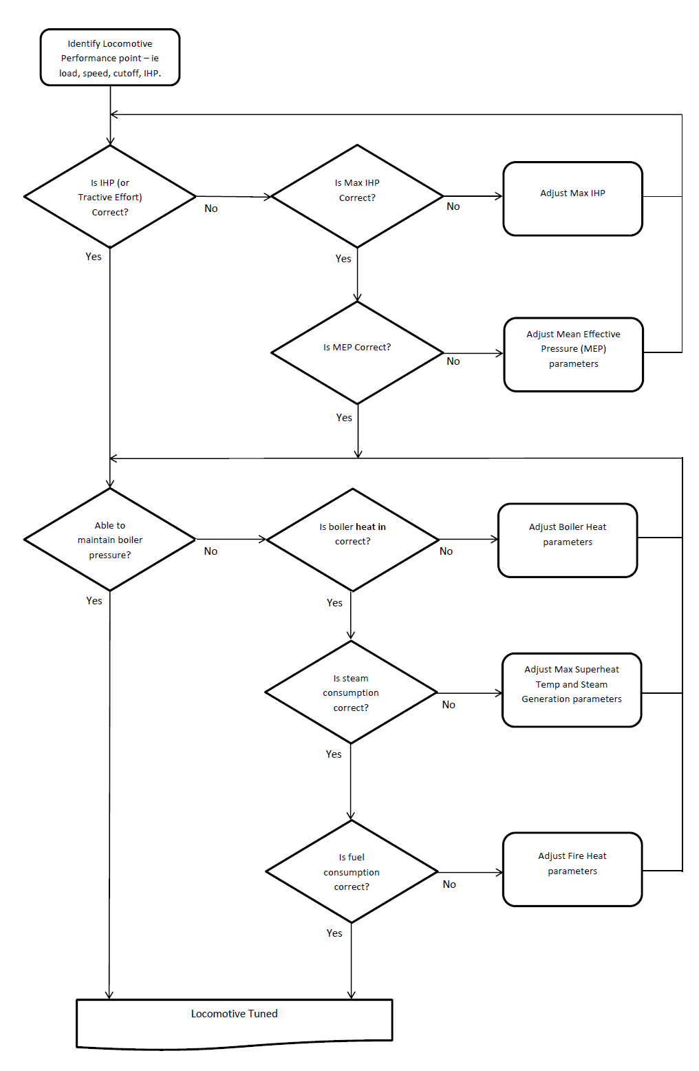
The above flowchart shows the recommended order to test and tune the model. It indicates the section of the steam model to adjust if IHP (Tractive Effort) or Boiler Pressure is incorrect.