Train Brakes
Aim - this section provides an overview of the operation and physics of typical brakes that might be fitted to a train.
To convert tons to kN = tons x 9.964 kN.
If you wish to provide any feedback on this page, please use the contact page. It would be great to have some feedback as this helps to ensure the accuracy of the information and models.
Index
Overview of Westinghouse Air Brake System
Net Braking Ratio (Braking Percentage)
Generic Air Brake Design Information
Overview of Vacuum Brake System
Overview of Steam Brake System
Useful References - Air Brakes
Useful References - Vacuum Brakes
Introduction
In the early days of operation, some trains, such as the "Rocket" did not have brakes applied to them. In order to stop the driver put the reverser into reverse and used this "reverse" steam pressure in the cylinder to bring the train to a stop.
Robert Stephenson invented the steam brake in 1833, which was applied to the locomotive and the tender. Hence after this time, trains typically had brakes fitted to the locomotive and tender, and special wagons, which were often called the 'brake van'. The brakes in these wagons were applied by the train guard (also known as the brake man) manually, generally when the locomotive driver sounded a pre-designated whistle code. Sadly as trains were operated at faster speeds, and with heavier loads this method of braking was found to be inadequate due to the slow application and response times to stop, and at the time contributed to a number of accidents, such as the one at Abbots Ripton. As a consequence, there were numerous calls for the introduction of a continuous braking system.
Over the years a number of continuous types of air brakes have been developed and used on trains. These include air and vacuum operated brakes. More recently, electrically operated brakes have been introduced to some rolling stock. Naturally the effort to fit continuous brakes to rolling stock was spread over many years, and often started with passenger stock. In some instances with slower, less important rolling stock air brakes were never fitted throughout the lifetime of the rolling stock. For example, in Australia there were coal hoppers still in service up to the 1980s that did not have continuous brakes fitted to them.
The Westinghouse brake system was a major breakthrough for the safe operation of trains. It has become the predominant type of brake system used by railways around the world. The Westinghouse system has evolved significantly since its invention in 1873, and there have been many system variations as it has been enhanced to cater for high speed and heavier trains.
Although the Westinghouse brake was the winner of two sets of brake trials in Britain, about two thirds of British Railway companies adopted the vacuum brake. Reasons being low cost, simplicity and ease of maintenance - (an ejector used to create a vacuum on a steam locomotive has no moving parts). Following the grouping of 1922 it became the standard brake of all of the four main line railway companies until superseded by air brakes in the 1970s. As well as use in Britain the vacuum brake was also exported to many British colonies and to lines in elsewhere supplied with British equipment. The vacuum brake was also the standard automatic brake used by Swedish Railways until the 1920s and by Austrian Railways until the 1930s.
Overview of Westinghouse Air Brake System
This information has been extracted from various Westinghouse and NSWGR publications, some of which may be found in the NSWGR Documents Section. Whilst a few different styles and types have been used, the following information should apply in general and give a reasonably close approximation of its operation.
Overview of Brake Systems
In the early days of railway operation, the locomotive and brakevan were the only vehicles fitted with brakes. Train operation required the locomotive driver and brakeman to co-ordinate their activities to control the train. After seeing a wreck in about 1867, a 22 year old George Westinghouse patented a "fail-safe" air brake system. If the pressure in the train brake pipe drops, either because the engineer applies the brakes or the brake pipe is broken for some reason, then the brakes are applied by air pressure from a reservoir in each car. The brakes can only stay open if the compressor is pressurizing the line.
During 1877 some locomotives and passenger cars were imported into the NSWGR from North America fitted with Westinghouse air brakes. From the 1880s Westinghouse Air Brakes were adopted as standard for NSWGR passenger cars. Some older cars were fitted with through air pipes, but no brake equipment. By 1904 most passenger stock was fitted with air brakes. Goods stock followed a similar process. Some privately owned coal hoppers, right up to their retirement in the late 1970s, did not have air brakes fitted. Over the years various refinements have been made to the Westinghouse brake. The overview on this page provides a simplified description of the brake operation and design. For more detailed information refer to the useful links section at the bottom of this page.
Passenger and Freight Car Brake System
The diagram below shows a typical Westinghouse train brake system for an older style passenger or freight wagon, and has been extracted from an Australian Westinghouse publication of the early 1950s.
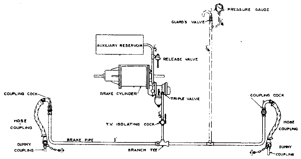
The principal elements of the brake system on a wagon are as follows:
Brake pipe
The brake pipe runs the full length of the train and supplies air pressure to the brake systems on each wagon, as well as provides relevant control signals to operate the brakes. Typically the normal operating pressure in the brake pipe is 75 to 80psi on passenger trains and 60 to 70psi on freight trains.
Brake cylinder
Applies force to the brake shoes on the car wheels. The brake cylinders are selected to provide the appropriate brake force for the weight and speed of the wagon.
In some instances for small stock, such as 4 wheel wagons, combined brake cylinder and reservoirs were used. For larger stock separate reservoirs and brake cylinders were typically employed.
Auxiliary reservoir
The auxiliary reservoir was used to supply air to operate the brake cylinder. Typically the auxiliary reservoirs and brake cylinders proportioned that an equalization pressure of 50psi will, be obtained from 70psi auxiliary reservoir pressure (brake pipe pressure). This typically equated to a triple valve ratio of 2.5. In some instances supplementary reservoirs were installed to provide additional air capacity.
Triple Valve
The triple valve has three duties to perform:
- Charge the auxiliary reservoir - whenever the pressure in the brake pipe is greater than the pressure of the auxiliary reservoir. Typically a triple valve should charge an auxiliary reservoir from 0 to up 70psi in about 70 sec.
- Apply the brakes - whenever the pressure in the brake pipe drops below 70psi, air will be allowed to flow from the auxiliary reservoir into the brake cylinder. Ordinarily, a brake pipe reduction of about 20psi will cause full pressure application of 50psi in the brake cylinder, and thus a full application of the brakes.
- Release the brakes - increasing the brake pipe pressure above the auxiliary reservoir will cause air to be exhausted from the brake cylinder, thus reducing the pressure in the brake cylinder. The auxiliary reservoir is re-charged during this operation.
An emergency application of the brakes is bought about by the rapid reduction in pressure of the brake pipe. It should be noted that guard of the train had a brake pipe release valve in the brakevan, which could be opened to drop the brake pipe pressure, and stop the train in the case of an emergency.
Brake System Refinements
Over the years a number of enhanced features have been added to the braking systems, and these include the following.
Grade Control
The purpose of the grade control valve is to slow down the rate of exhaust of the brake cylinder finally retaining a small amount of pressure, thus enabling a recharge or the braking system to be obtained on heavy grades without the necessity of using hand brakes to prevent the train accelerating at too fast a rate.
Older wagons typically had no grade control or had manually operated valves. Typically the Grade Control Valves had the following three positions on them:
- EX - Normal exhaust position. Brakes operate as if no grade control is available. Air is released from the brake cylinder in approximately 20 sec after full application.
- IP - Intermediate Pressure position. Used for light grades or empty or lightly loaded vehicles on heavy grades. Air is released from the brake cylinder in approximately 55 sec after full application.
- HP - High Pressure position. Used to work over heavy falling grades. Air is released from the brake cylinder in approximately 105 sec after full application, and 7.25 psi of pressure is maintained in the brake cylinder.
Load Compensation
The purpose of using this equipment is to use normal braking force when the vehicle is empty, but to provide additional braking force when the vehicle is loaded. Loaded wagons can use larger braking forces as the Adhesive weight of the wagon is higher, and wheel skid is less likely to happen. If the same loaded wagon braking forces were used on empty wagons, it is highly likely, due to the light adhesive weights of the wagon, that wheel skid would occur.
Older wagons typically had no grade control or had manually operated valves. Typically Load Compensation Valves had the following two positions on them:
- E - Empty wagon. No load compensation.
- L - Loaded wagon. Load compensation applied.
Modern stock tends to have automatic load compensation equipment which uses a proximity switch or pressure switch to differentiate between load and unloaded wagons.
Naturally, as wagons without load compensation used the unloaded (tare) weight for calculating braking forces, special care needed to be taken by the driver, as the braking power of the train was less than that for a loaded train with load compensation.
Wheel Slide Protection, which is described in the following extract from a XPT (High Speed Train) manual has been added to a number of modern trains.
"During braking wheelslide control is effected throughout the train by additional equipment on each vehicle. In the piping to each pair of brake cylinders are fitted electrically operated dump valves. When axle rotations which are sensed electrically, differ by a predetermined speed the dump valves are operated releasing brake cylinder pressure to both axles of the affected bogie.
Dump valve operation will cease when differences in axle rotations arewithin specified limits or the axle accelerates faster than a specified rate. The dump valve will only operate for a maximum period of seven seconds after which time it will be de-energised and the dump valve will not re-operate until the train has stopped or the throttle operated.
Dump valve operation is prevented under the following conditions:-
(i) When the Power Controller is open.
(ii) When Brake Pipe Pressure has been reduced below 250 kPa (36.3 psi)."
Some system were able to disable condition ii) above, and operate down to all brake pipe pressures.
If you wish to see WSP in operation then have a look at this film.
Miscellaneous Brake System Impacts
Train Pipe Leakage
The brake system tends not to be a perfectly closed system, and it is possible for air leaks to develop in the system. The most likely place for leakage is in the couplings due to the seals becoming damaged. Air leakage can result in a slow decline in air pressure in the train brake pipe, which will increase the application of the brakes over time. In most brake positions this leakage is compensated for, and air from the reservoir is used to replace air which leaks out of the system. In older brake systems, such as the A-6-ET system, the LAP position isolated the train brake pipe from the reservoir which prevented air leakage being compensated for, and thus the train brake pipe slowly decreased in pressure. In newer systems the LAP position is often self-lapping, i.e. it compensates for the air leakage.
Most railway companies require the crew to undertake leakage tests when marshalling a train, and this test is deemed a success if the air leakage is less then 5psi/min.
Locomotive Brake System
The diagram below shows a typical Westinghouse train brake system for a locomotive, and has been extracted from an Australian Westinghouse publication of the early 1950s.
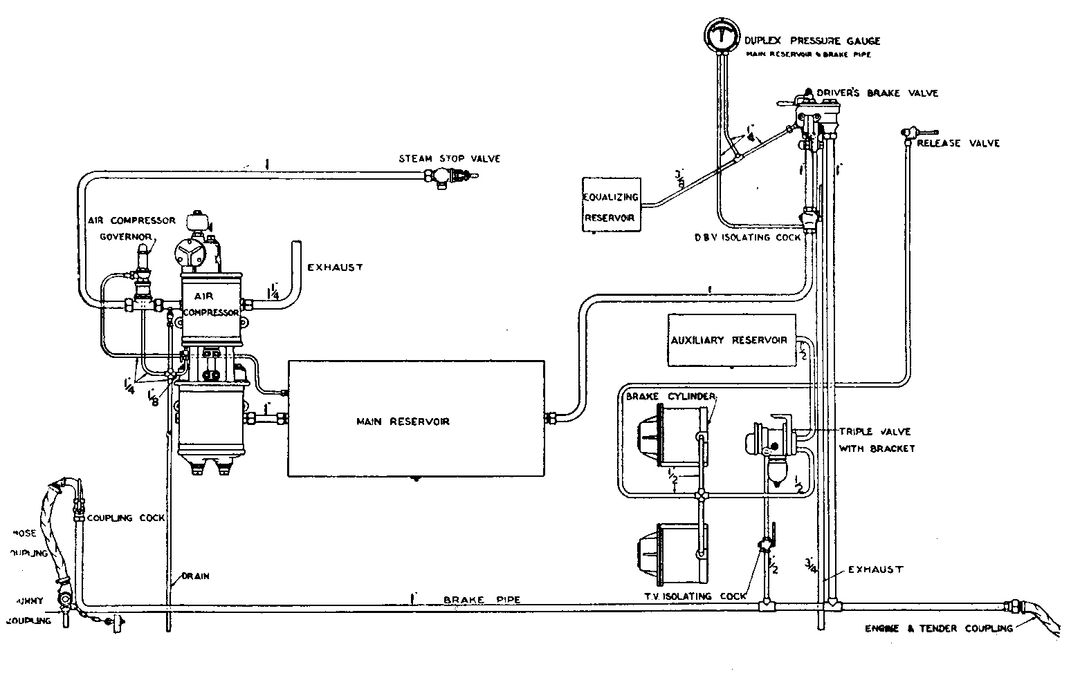
The brake system on the locomotive consisted of two separate components:
- Locomotive brake - were the elements that applied brake force to wheels of the locomotive to bring it under control. These were similar to those described above for the freight or passenger wagon.
- Brake control - were the elements that varied the brake pressures to signal the brake cylinders to apply or release the brakes.
The principal elements of the train brake control are as follows:
Compressor
Supplied compressed air as appropriate for the operation of the train brake.
Main Reservoir
Provide air storage for operation of the train brakes. Typically the pressure in the main reservoir was maintained at 100psi.
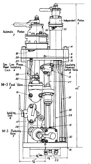
Drivers control stand
Typically NSWGR steam locomotives were fitted with A-6-ET (Engine and Tender) brake equipment, whereas older diesels were fitted with A-7-EL brake valves. This equipment allowed independent operation of the locomotive and tender brake compared to the rest of the train. The locomotive brake may be applied or released, in whole or in part, with or independently of the train brakes, and this without regard to the position of the locomotive in the train. This allowed the driver some flexibility in applying light brake applications or in some circumstances holding the locomotive and tender brakes on after releasing the train brake.
The brake valve stand contained two brake valves, an automatic brake (controls all cars in the train) and an independent brake which controlled the locomotive and tender brakes only. A typical brake valve stand is shown in the diagram below, with the automatic brake on the left hand side, and the independent brake on the right hand side.
The operating positions of the A-6 and A-7 brake valve are shown in the diagrams below. The Automatic brake valve (Train brake) is shown on the left hand side of the diagram, whilst the Independent brake valve (Engine Brake) is shown on the right side of the respective diagrams.
 A-6 Brake Valve.
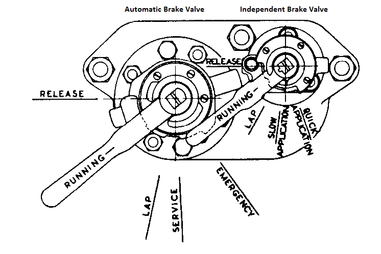 A-7 Brake Valve.
Automatic brake valve (Train Brake)
The automatic brake valve, which controlled the train brakes had 5 positions of operation as follows:
- Release - In this position the brake valve releases the train brakes, and recharges the brake system (auxiliary reservoirs, etc.) on the train. The locomotive brake, if applied, is permitted to release at a retarded rate so that the tendency for the engine and tender to surge away from the train is suppressed.
- Running - In this position, the train brake pipe will be maintained at the normal running pressure, in this instance 70 psi. This holds the brakes in the released state, and allows for small amounts of pipe leakage. This is the normal operating position for the brakes.
- Lap (or Neutral) - In this position the train brake system is isolated from the main reservoir, and thus over time, pressure in the system may decrease due to leaks. In this position, the brakes will remain in the state that they were set for, but eventually they will start to apply as leakages in the system start to reduce air pressure. When the brake handle is move from the Running position to the Lap position, a pressure reduction of approximately 7 psi is applied.
- Service - In this position the brakes are applied under normal pressure.
- Emergency - In this position, the air in the brake pipe is exhausted to atmosphere to cause a heavy reduction in brake pipe air pressure, resulting a heavy brake application.
Independent brake valve (Locomotive and Tender Brake)
The independent brake valve, which controlled the engine and tender brakes had 5 positions of operation as follows:
- Release - In this position the brake valve rapidly releases the locomotive and tender brakes, independently of the train brakes.
- Running - In this position, the locomotive and tender brakes are "slaved" to the train brake system, so that if the train brakes are applied or released, the engine and tender brakes will go to the same state. This is the normal operating position for the engine and tender brakes.
- Lap (or Neutral) - In this position the train brake system is isolated from the main reservoir, and thus over time, pressure in the system may decrease due to leaks. In this position, the brakes will remain in the state that they were set for, but eventually they will start to apply as leakages in the system start to reduce air pressure.
- Slow application - In this position the brakes are applied slowly to allow light brake applications.
- Quick application - In this position, the air in the brake pipe is exhausted more quickly to result in a more rapid brake application.
When releasing the brakes, a "graduated" approach can be used, so that small increases in brake pipe pressure will result in a small release of the brakes.
If you want information on other types of brake valves, such as the Westinghouse 26-L or 24-RL models, see alternate brake valves page.
SME (also called SEM) Brake System
The SME is essentially a straight air-brake equipment having an automatic emergency feature. The simplicity of the straight air brake is available for ordinary service operation, while the addi- tional safety features of the automatic application of the brake is provided in case of a break-in-two, bursting of a hose, etc. The system is designed for use on short trains of not more than two cars in length.
The chief features of the equipment as set forth in the manufacturer's pamphlets are as follows:
- Straight air operation for service stops.
- Brake cylinder release operates locally, i.e., through the emergency valve on each car.
- Prompt service application and release operations due to design of the emergency valve.
- Automatic maintenance of brake cylinder leakage.
- Uniform brake cylinder pressure, independent of variations in piston travel or leakage.
- Practically uniform compressor effort insured without the necessity of a governor synchronizing system.
- Automatic application of the brakes in case of ruptured piping, burst hose, or parting of the train.
- Retarded release after an emergency application, as a penalty to discourage the unnecessary use of this feature.
- One size of emergency valve for any size of brake cylinder.
- Possibility of conductor setting the brakes in emergency by means of conductor's valve.
Double Heading of Locomotives
When multiple locomotives are being used on the one train, regardless of where they are in the train, except for the lead locomotive, the brake Valve Isolating cocks must be closed, and both brake valves should be in the Running position. This will allow the lead locomotive to operate it brakes. It should be noted that the main reservoir on all but the lead locomotive will remain at full pressure.
Prototype NSW brake settings
In setting the brakes as accurately as possible the following prototypical information has been considered. This information has been compiled from various New South Wales Government Railways (NSWGR) publications. You may however substitute information from any other railway systems to achieve a more localised rolling stock setting.
The brakes were set up to graduate off, and but not on.
Net Braking Ratio (Braking Percentage)
Train Brake
The "net braking ratio" (NBR) of a vehicle is defined as the ratio of the total force applied to the brake block (shoe) on the wheels, proportional to the total weight of the vehicle.
When this is expressed as a percentage it is known as the "braking percentage" and is the figure used to express the braking value of a vehicle. In the case of goods vehicles, from older publications, the usual figure is 60 - 75% of tare (empty) weight and for passenger cars 75 - 90%.
When expressed as a formula:
Net Braking Ratio (NBR) = Brake Shoe Force (BSF) / Tare (unloaded) Vehicle Weight (W)
Thus to determine the ideal Brake Shoe Force applied to the wagon wheel brake shoe, we have the following:
BSF = NBR * W
This is the force applied by the rolling stock brake cylinder and brake levers. To find the actual force applied to the wheels, we need to take into account the co-efficient of friction of the brake shoe, thus the above figure also needs to be multiplied by co-efficient of friction.
BRF = BSF * CoF
Refer to the next section "Effect of Brake Shoe Friction" for a more detailed explanation on friction coefficient.
High values of NBR will result in high brake forces being applied to the wheels of the rolling stock, causing the wheels to "lock up" and to skid along the tracks. Various publications provide guidance on the desired values for NBR under different brake configuration scenarios and brake shoe types. The following values are examples of the values recommended:
- Passenger cars - 90%, Freight Cars - 70%, Tenders - 100%, Locomotive drivers - 75% of drive wheel weight, Locomotive truck - 75% of truck wheel weight. (Ref pg 99 of "Air Brakes" by Ludy.)
- Freight Cars - 50% (Cast Iron shoes), Freight Cars - 30% (COBRA shoes) (Ref pg 125 of "Train Accident Reconstruction and FELA and Railroad Litigation" )
- Freight Cars - 38%. (Ref AAR Standard S-401-99)
It should be remembered that OR only models the direct brake force applied to the wheels of the wagon.
Rules of Thumb that can be used in Open Rails -
Typically, for NSWGR stock, we will assume NBR values of 60% for Goods cars, 80% for Passenger Carriages, 60% for Locomotive Tenders, and 75% for locomotives.
For NSW we can assume that most pre-1970 stock will have cast iron shoes, and thus a value of 20% for the co-efficient of friction was considered appropriate.
For more modern NSW NBR recommended values refer to pg 14 of ARTC - Freight Vehicle Specific Interface Requirements WOS 01.400.Alternatively the Association of American Railroads (AAR) has suggested a band (maximum and minimum) set of values for new and rebuilt freight wagons in their 1999 standard, S-401-99. The suggested values are shown below:
Car Type |
Loaded Net Braking Ratio |
Maximum Empty Braking Ratio |
Minimum Hand Braking Ratio |
|
|---|---|---|---|---|
Minimum |
Maximum |
|||
TOFC/COFC |
11% |
13% |
38% |
10% |
All Other |
8.5% |
13% |
38% |
10% |
It is recommended that the values be tested to ensure that they give a good braking "feel" to the wagon, and don't cause the wheels to lockup and skid on the rails.
Thus the calculation of the Brake Shoe Force might look like this:
Brake Shoe Force = {(0.6 or 0.8) * Tare (or empty) Weight (lbs)} lbf
Handbrake
The NBR for a handbrake in rolling stock specifications may be between 13 - 28% of the fully loaded weight of the vehicle. Typically we might assume a NBR figure of 20% for both Goods and Passenger Stock.
Thus -
Brake Shoe Force = {0.20 * Fully Loaded Weight (lbs)} lbf
Effect of Brake Shoe Friction
As the wheel on a wagon rotates, the amount of stopping force that can be applied will be dependent upon the brake cylinder force, construction of the brake levers, and the material type of the brakeshoes installed on the wagon. The brakeshoes will have a certain amount of friction (or adhesion) which will reduce the amount of stopping force that is actually applied to the wheel. For example, a single cast iron brakeshoe, will have a "Mean" coefficient of friction (CoF) of approximately 13% (0.13). As can be seen from the graphs below, the CoF varies with the speed of the vehicle, and at low speeds the actual CoF can be as high as 50% (or 0.5), so that the braking force calculated in the formula above will be effectively almost tripled at low speeds, compared to higher speeds. For ease of calculation the "Mean CoF" was generally used in the above formula for brake design. The diagram below demonstrates the impacts of speed, and brakeshoe type on the CoF for different brakeshoe materials.
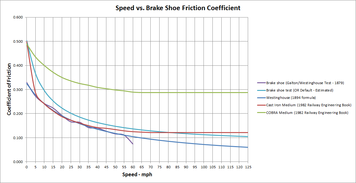
In the diagram, the curves shown represent the following:
- Purple - based upon a series of early tests undertaken by Captain Douglas Galton, an engineer, in conjunction with Westinghouse. This was an empirical (based upon actual tests) set of results. Note that the maximum speed of the results reflects the early limitations on speed. These results were based upon tests on cast iron brakeshoes.
- Dark Blue - based upon an empirical set of test results, Westinghouse developed a formula to describe the friction of cast iron brakeshoes.
- Red - a modern derivation of friction for cast iron brakeshoes from a railway engineering reference book.
- Green - a modern derivation of friction for COBRA (COmposition BRAkes made of composite materials) brakehoes from a railway engineering reference book. These are fitted to most modern types of locomotives.
- Light Blue - an estimation of brakeshoe friction that is used in Open Rails as a default value for the brake adhesion model.
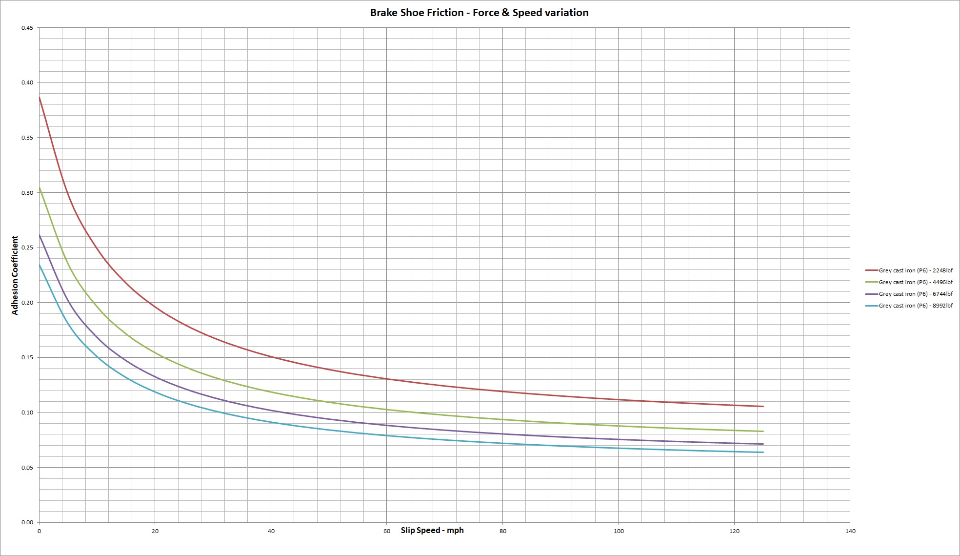
In addition to the train speed, the force applied to the brake shoe, and the temperature of the shoe can also impact the friction between the wheel and the brake shoe. Trains drivers are encouraged not to make severe brake operations, and frequent operations in order to attempt to maintain brake shoe temperatures within reasonable bounds, to limit the impact of high temperatures on there operation. The graph below shows the impact on cast iron brakes for different speeds and pressures.
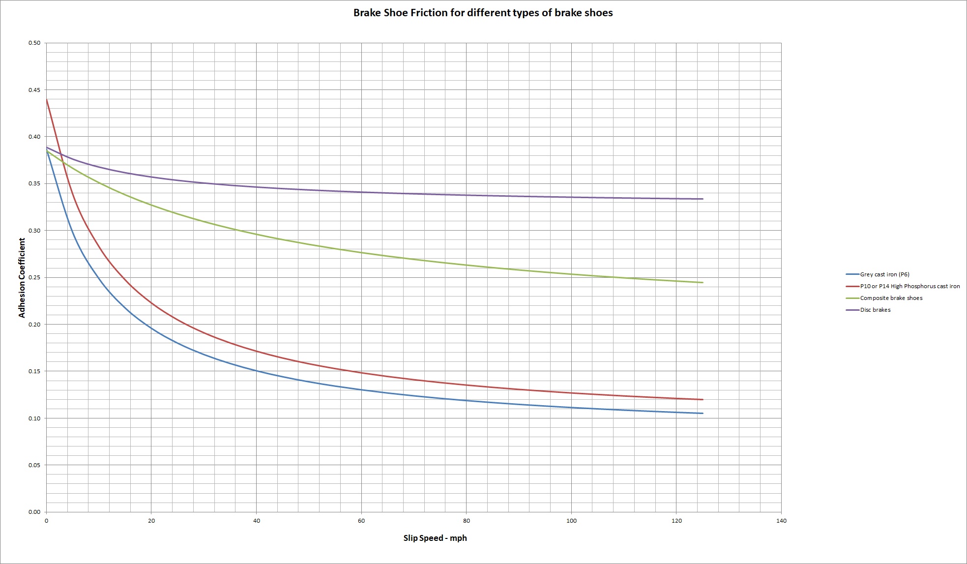
In the early days of railway operation cast iron brakes shoes were the norm, however as train speeds increased there was a transition to different brake shoe materials in an attempt to increase the "Mean CoF" of the train brakes. This transition saw the addition of phosphorus to the cast iron to improve wear and friction. Composite materials are now often used, and disc pad brakes are now used in some applications, such as high speed train operations. The graph below shows the improvement in friction, especially at higher speed for these different types of materials.
Thus trains travelling at higher speeds, due to the reduced values of friction, will require more force to be applied to the brakeshoe then at lower speeds. For example, if a brake cylinder force of 10,000lbf is applied to a cast iron brakeshoe with the train travelling at say 5mph, then from the diagram above with a coefficient of friction of 0.288, approximately 2880lbf of stopping force will be applied to the wheel. If the same brake cylinder force is applied at 40mph, then as the friction value has reduced to 0.142, the corresponding stopping force applied to the wheel will only be 1420lbf, or approximately 50% of the force applied at the lower speed.
This means that train drivers will need to exercise great care when their trains are travelling at high speeds, as it is possible for the train to become "uncontrollable", and not stop in the desired time to avoid an accident.
When the retarding force between brakeshoe and wheel becomes greater than the adhesion force between the wagon wheel and rail the wheel will skid, and as the CoF is high at low speeds, wheels are more likely to be skidded at slower speeds. In most cases skidding takes place when the vehicle is moved from rest with the brake applied, when, since the speed of the wheel relative to the brake shoe is zero, the co-efficient of friction is at its highest value. This would, of course, occur only due to failure of brakes to release, to a hand brake being applied, or to any other cause which may prevent the wheel from rotating.
Frequent use of the brakes also results in heating of the brake shoes which can result in a decrease in the CoF.
Generic Air Brake Design Information
For instances were specific brake parameters are not know the following information may be used instead to ascertain an appropriate approximation for some brake parameters. Always use known information where available. In the tables below some values have been calculated based upon other values in the table, and are shown in green figures in the table.
Standard Brake Cylinder Size
The following table shows the maximum force exerted by the cylinder when the pressure in the cylinder is fully charged to 50psi. The required brake cylinder force can be calculated with the wagon brake force and the brake cylinder size calculators above. Once this is done an estimation can be made of the brake cylinders that need to be fitted to a locomotive, carriage or wagon, by comparing the kN force result with the closest relevant figure in the right hand column of the table below. If the calculated value exceeds the value shown in the right column, as may be the case for some heavy stock such as a locomotive of modern bulk hoppers, then multiple brake cylinders can be used to achieve the most appropriate result. For example, a NSW C38 class locomotive was fitted with 2 x 15" Brake Cylinders, whilst the tender had 2 x 12" brake cylinders. For multiple brake cylinders multiple the brake cylinder force by the relevant number of cylinders required, ie 2 off 12" = 50.264kN. Cars and wagons can have can have brake cylinders mounted on each bogie (truck).
Brake Cylinder Size |
Force exerted |
Cylinder capacity (@ 8" travel) |
|||
|---|---|---|---|---|---|
(in) |
(lbf) |
(tonf) |
(kN) |
(cu in) |
(cu ft) |
6 |
1,400 |
0.625 |
6.227 |
226.2 |
0.131 |
8 |
2,500 |
1.116 |
11.120 |
450 |
0.260 |
10 |
3,900 |
1.741 |
17.348 |
675 |
0.391 |
12 |
5,650 |
2.522 |
25.132 |
950 |
0.550 |
14 |
7,700 |
3.437 |
34.251 |
1,280 |
0.741 |
16 |
10,000 |
4.464 |
44.482 |
1,650 |
0.955 |
18 |
12,700 |
5.670 |
56.492 |
2,085 |
1,206 |
For locomotives, the suggested size of brake cylinder used for different weights on driving wheels is as follows:
- 8" cylinders - up to 40,000 pounds on drivers
- 10" cylinders - 40,000 to 85,000 pounds on drivers
- 12" cylinders - 70,000 to 115,OOO pounds on drivers
- 14" cylinders - 110,000 to 170,000 pounds on drivers
- 16" cylinders - 145,000 to 225,000 pounds on drivers
- UK = 350m = 20inHg.
- Aus = 923m = 19inHg.
- USA = 4,301m = 14inHg.
- The Vacuum Break(sic) must be used for the ordinary stoppage of the train by the Engine-driver, who must apply it gradually, and not suddenly, nor with full force, except in the case of an emergency.
- Just before coming to a stand, the Vacuum Break(sic) must be eased off by partially re-creating the vacuum so as to prevent a rebound of the vehicles, or undue strain on the couplings. The Steam Break(sic) must not be used independently of the Vacuum Break(sic).
- Steam must not be applied to move the train forward after the Breaks(sic) have been applied, either slightly of fully, until the Breaks have been released throughout the train.
Standard Size Auxiliary Reservoirs
The following table shows the recommended sizes for relevant brake cylinder sizes in different applications. Locomotives could be fitted with both brakes on the drive wheels, and the leading and trailing trucks or just on the drive wheels. For small stock, such as 4 wheel wagons and narrow gauge stock, combined brake cylinders and reservoirs were available. Typically the 6 inch brake cylinders and compressors were used on narrow gauge stock.
Brake Cylinder Size (in) |
Auxiliary Reservoir Capacity |
|||||
|---|---|---|---|---|---|---|
Driver |
Truck |
Tender |
Passenger |
Freight |
(cu in) |
(cu ft) |
|
6 |
|
6 |
|
772 |
0.447 |
|
8 |
|
|
|
1,180 |
0.682 |
6 |
|
8 |
8 |
|
1,476 |
0.854 |
|
10 |
|
|
|
1,774 |
1.027 |
8 |
|
|
|
|
2,145 |
1.241 |
|
12 |
10 |
10 |
|
2,457 |
1.422 |
10 |
|
12 |
12 |
|
3,096 |
1.792 |
12 |
|
14 |
14 |
|
4,476 |
2.590 |
14 |
|
16 |
16 |
|
5,724 |
3.312 |
16 |
|
|
18 |
|
7,436 |
4.303 |
18 |
|
|
|
|
8,577 |
4.963 |
|
|
|
|
6 comb |
772 |
0.447 |
|
|
|
|
8 comb |
1,620 |
0.973 |
|
|
|
|
10 comb |
2,800 |
1.620 |
|
|
|
|
8 detach |
1,620 |
0.973 |
|
|
|
|
10 detach |
2,800 |
1.620 |
Main Reservoir Sizing
The main reservoir varies in size according to the kind of service - freight or passenger - in which the engine is employed. In the best practice, a main reservoir of not less than 40,000 cu. in. capacity for passenger, and from 50,000 to 70,000 cu. in. for freight, service is used. If the train is long and the main reservoir small, a high pressure must be carried in the latter in order that it may equalize with the brake pipe at a sufficiently high pressure to promptly release the brakes and recharge the auxiliaries. When the main reservoir is large, a much lower reservoir pressure can be carried, and the pump can also store a greater quantity of air while the brakes are applied. When, therefore, the main reservoir is small, the pump must work both faster (or longer) and against a higher pressure, either of which tends to cause overheating. A much higher pressure is required in the main reservoir than in the brake pipe, not only to release brakes, but also to force the air through the brake pipe in the shortest time possible and thus release all brakes on a long train promptly and as nearly simultaneous as possible.
Steam Driven Air Compressor - Sizing
The following table is provided as a guide of the size of compressor required to adequately maintain pressure in the selected main reservoir. This table is based upon recommendations for freight trains.
Main reservoir Size (cu in) |
Main reservoir Size (cu ft) |
Compressor Type |
|---|---|---|
16,500 |
9.549 |
1 off 8in |
50,000 |
28.935 |
1 off 9.5in |
60,000 |
34.722 |
2 off 9.5in |
65,000 |
37.615 |
1 off 11in |
70,000 |
40.509 |
2 off 11in |
70,000 |
40.509 |
1 off 8.5in Cross-compound |
The following table provides some of the core specifications of the standard compressor types and specific units used by the NSWGR. Units used by NSWGR are shown in the columns identified by an alpha code (E, F, B, etc). These specifications can be used to identify the appropriate value for "Compressor Free Air" to be used in the reservoir charging rate calculator above.
|
Standard Compressor (in) |
Cross Compound Compressor (in) |
|||||||
|---|---|---|---|---|---|---|---|---|---|
|
6 |
8 |
E |
9.5 |
F |
B |
11 |
8.5 |
10.5 |
Steam Cylinder Dia (in) |
6 |
8 |
8 |
9.5 |
10 |
10 |
11 |
HP-8.5, LP-14.5 |
HP-9.5, LP-16.75 |
Air Cylinder Dia (in) |
6 |
8 |
8.5 |
9.5 |
10 |
10.5 |
11 |
HP-9, LP-14.5 |
HP-9.5, LP-14.5 |
Length of Stroke (in) |
10 |
10 |
10 |
10 |
10 |
10.25 |
12 |
12 |
12 |
Speed (strokes/min) |
120 |
120 |
120 |
120 |
120 |
120 |
100 |
131 |
131 |
Air Displacement (cu ft) |
19.5 |
35 |
39.5 |
49 |
|
|
66 |
150 |
150 |
Free Air (cu ft/min @ 100psi) |
12.2 |
22.0 |
24.8 |
28.0 |
|
|
45.0 |
|
|
Overview of Vacuum Brake System
This information has been extracted from various publications, some of which may be found in the Useful References Section. Whilst a few different styles and types have been used, the following information should apply in general and give a reasonably close approximation of its operation.
The first vacuum brake was a "straight" or non-automatic vacuum brake. because of safety issues with type of brake configuration, they lost popularity and were replaced with automatic vacuum brakes.
Non-automatic (Straight) Vacuum Brake
The straight brake was a very simple arrangement consisting of a brake pipe running the length of the train, and a brake cylinder on each car. A vacuum was created in the brake pipe which applied force to the brake shoes (apply the brakes) to stop the train. To release the brakes the vacuum was destroyed, and the pipe filled with air.
The main disadvantage of this system was that a break in the train pipe would prevent the brakes from being applied, and hence this was seen as a major safety issue, and these types of system lost favour with railways. The automatic brake had the reverse operation (ie the vacuum in the brake pipe released the brakes, and a breakage in the brake pipe caused the brakes to apply.
The two most common examples of these types of brake were the Eames and Hardy brake systems. Some examples of these types of brakes still exist today.
Automatic Vacuum Brake
In its simplest form, the automatic vacuum brake consists of a continuous pipe - the train pipe - running throughout the length of the train. In normal running a partial vacuum is maintained in the train pipe, and the brakes are released. When air is admitted to the train pipe, the air at atmospheric pressure acts against pistons in cylinders in each vehicle. A vacuum is sustained on the other face of the pistons, so that a net force is applied. A mechanical linkage transmits this force to brake shoes which act on the treads of the wheels.
Carriage and Wagon Brake System
The diagram below shows the main parts of the vacuum brake system on a wagon.
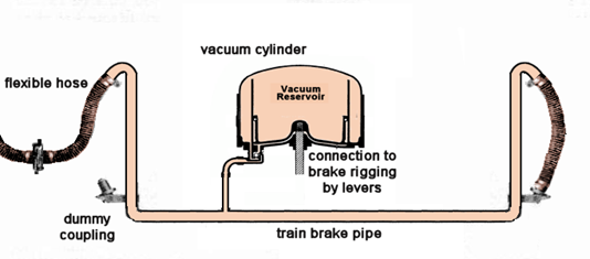
The principal elements of the brake system on a wagon are as follows:
Brake pipe
The brake pipe runs the full length of the train. It provides the vacuum that operates the brakes. Most railway companies used a vacuum of 20 or 21 InHg (inches of mercury). The GWR used a greater vacuum of 25 InHg.
Vacuum Cylinder
The vacuum cylinder consists of two parts. The lower part is the "brake cylinder" and movement of the piston within the brake cylinder applies force to the brake shoes on the wagon wheels. A series of levers connect the piston to the brakes in order to provide the appropriate brake force for the weight of the wagon.
Above the brake cylinder is the "vacuum reservoir". (The equivalent of the auxiliary reservoir in an air brake system.)
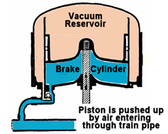
When air enters the brake pipe the difference in pressure between the underside of the brake piston and the vacuum reservoir above provides the force that operates the brakes. Some heavier carriages and locomotives had larger brake cylinders with a separate vacuum reservoir.
Air may be admitted to the pipe through the placing the driver's brake valve in the apply position or in an emergency through the guard's brake valve or by the use of the passenger alarm. If the train becomes divided then air will enter the brake pipe and the brakes will be applied automatically.
To release the brakes then a vacuum must be created in the train pipe. The ejector or exhauster is used to do this. When the driver's brake valve is placed in the release position then the train pipe is connected directly to the ejector or exhauster or high vacuum reservoir.
Dummy Coupling
At the end of the train the flexible hose used to connect the wagons together is placed on a dummy coupling (or plug). This seals the train pipe and there is no need for a cock.
Brake System Refinements
Direct Action Valves
It takes some time for automatic brakes to come into operation along the length of a train. Following an accident at Slough in 1900, where an express overran two sets of signals the GWR designed a direct action valve to speed up the application of vacuum brakes. Direct action valves allow air to enter the brake cylinder directly if the vacuum in the train pipe falls below a certain level. Direct Action valves were fitted to all new GWR passenger carriages from 1906.
Other companies were slow to follow. The LNER introduced Direct Action valves on its streamlined high speed stock from 1935, but did not fit them to general service stock. The LMS started to fit Direct Action valves from about 1939. All post nationalisation passenger carriages were fitted with Direct Action valves. Goods wagons were not normally fitted with such valves.
Load Compensation
Some British Railways built vacuum braked goods wagons included load compensation. This took the form of a second brake cylinder so that the empty wagon operated with only one brake cylinder, but a second brake cylinder could be brought into use, by means of a lever, when the wagon was loaded.
Locomotive Brake System
A number of different braking arrangements were applied to locomotives. The diagram below shows the arrangement for a locomotive, and has been extracted from "A Manual of Steam Locomotive Restoration and Preservation" by D.W. Harvey in the early 1950s.
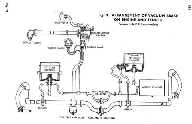
Locomotive Brakes
Many steam locomotives fitted with vacuum train brakes, used steam brakes (or air brakes) for the locomotive and tender. Most vacuum braked diesel and electric locomotives use air brakes for the locomotive. In these cases when the locomotive was hauling a train, the locomotive brakes were controlled by changes in the vacuum in the train pipe. Some steam locomotives were fitted with vacuum brakes and these operated in a similar way to those fitted to carriages and wagons. The only difference was that there was a release valve on the locomotive and/or tender. This allowed air to be admitted to the vacuum reservoir. As a result the brakes could be released without releasing the train brakes.
Ejector(s)
Vacuum brake systems suffer from leakage to a far greater extent than air brake systems. To maintain the vacuum against leakage a "small ejector" was normally provided on steam locomotives. The driver could adjust the setting of the small ejector to adjust for leakage depending on train length. Some steam locomotives were fitted with a vacuum pump in addition to (or in place of) the small ejector. The vacuum pump was worked from the crosshead and hence could only maintain the vacuum when the train was moving. In diesel and electric locomotives the vacuum is generally maintained by an electrically driven exhauster that operates automatically. (In some diesel locomotives and multiple units the exhauster is driven by the engine crankshaft. In such cases the exhauster operates continuously when the engine is running, charging a high vacuum reservoir. When the engine is running at low speed a vacuum can still be created or maintained by connecting the train pipe to the high vacuum reservoir).
All steam locomotives had one or two ejectors. These were used to create a vacuum in the train pipe. Locomotives with two ejectors had a large ejector to quickly release the brakes and a small ejector to help maintain the vacuum against leakage. Some locomotives also had a vacuum pump which helped to maintain the vacuum when the train was in motion.
Driver's Brake Valve
The driver's brake valve controls the train brakes. Most steam locomotives had simple ON / OFF valves. In the ON position the brake valve was open and air was able to enter and apply the brakes. In the OFF position the valve was closed to the atmosphere and the brake pipe connected to the ejector(s). More modern brake valves have a lap position or may be self-lapping allowing the driver to select and maintain a given vacuum.
Some brake valves integrated the operation of the (large) ejector with the operation of the brake valve. These had three positions: ON / RUNNING / OFF. The ON position was used to apply the brake. The RUNNING position connected the brake pipe to the ejectors and allowed the driver to adjust the (small) ejector to compensate for leaks or release the brakes after a service stop. The OFF position operated the (large) ejector to provide a quick release of the brakes.
Loss of Brake Effectivity at Altitude
The vacuum brake relies on the creation of a pressure differential to force the brake cylinders to apply force to the wheels. At sea level this pressure atmospheric pressure (~ 14.6psi), however as the altitude increase, the atmospheric pressure decreases. This means that at higher altitudes it is not possible to create effective pressure differentials (vacuum), and hence the vacuum brake will not work.
As an example, the relative vacuums that can be created at the different highest altitudes for a couple of various countries is shown below:
Operation of Vacuum Brake Systems
Train braking systems were required to stop large loads, and therefore were not designed to stop trains in short distances. Additionally the time to release and apply the brakes could take several minutes. Therefore it was important that the driver operated the brakes system as efficiently as possible to achieve the best performance as possible.
Making Service StopsStation stops should not be made by a violent application of the brake, but by a destruction of vacuum of, say, from 5 to 10 inches, which should be recreated slowly as the train comes to rest, by placing the handle in the running position.
By having the vacuum nearly restored at the end of the stop, "jerking" is prevented, and the brake may release without the use of the large ejector.
Southern Railway (from Southern Railway Magazine Vol 7 1929):
Station stops should not be made by a heavy application of the brake, but by a destruction of the vacuum of from 5 or 10 to 15 inches. This should be recreated as the train comes to rest by placing the handle in the "running position".
LNWR instructions to Engine-drivers 1921:
5. STOPPING -
Unless you have a very long train or a very leaky vacuum brake system you will rarely need to use the large ejector on steam locomotives or the release / exhauster speed up position on diesel or electric locomotives.
Coupling and UncouplingBefore attaching or detaching any vehicles you should make sure that the vacuum has been completely destroyed in the train pipe. Afterwards you will need to restore the vacuum in the train pipe (and vacuum reservoirs). This should be done by using the (large) ejector on full power or by placing the brake handle into the release position. When sufficient vacuum has been created you should return the brake to the running position or turn off the large ejector.
When a locomotive working at 20 or 21 InHg vacuum is coupled to rolling stock that has previously been hauled by a (GWR) locomotive operating at 25 InHg then it will be necessary to reduce the vacuum in the vacuum reservoirs on all the vehicles before the brakes can be released.
Overview of Steam Brake System
A steam cylinder was fitted to both the locomotive and tender which was connected to the pull rods for the brake shoes, and in this way, when steam was admitted into the steam brake cylinder the brakes would be applied. The handbrakes and steam brakes could be applied independently of each other.
It was necessary to provide a means of removing steam leakage around the cylinder piston, as well as any condensation.
In more modern brake systems, the steam brake was linked to the vacuum or air brake train brake. Hence operation of the train brake, could also cause the steam brake to operate.