Introduction to Steam Train Physics
Aim - this section describes the general key physics of Steam Locomotives operation.
Index
Typical Performance Criteria for Steam Locomotives
Steam Cylinder Indicator Diagram - Single Expansion (Simple) Locomotive
Steam Cylinder Indicator Diagram - Double Expansion (Compound) Locomotive
Indicator Diagram Interpretation
Steam Locomotive Booster Engine
Typical Performance Criteria for Steam Locomotives
A number of performance measures are typically used to describe the capabilities of a steam locomotive, and soem of these are described below.
Tractive Effort
Tractive Effort is created by the action of the steam against the pistons, which, through the media of rods, crossheads, etc., cause the wheels to revolve and the engine to advance. Note the tractive effort will decrease as the speed increases due to the decrease in the M.E.P.
Tractive Effort is a function of mean effective pressure of the steam cylinder and is expressed by following formula for a simple locomotive. Geared and compound locomotives will have slightly different formulae.
Where:
Cyl = number of cylinders
TE = Tractive Effort (lbf)
M.E.P. = mean effective pressure of cylinder (psi)
D = diameter of cylinder (in)
S = stroke of cylinder piston (in)
D = diameter of drive wheels (in)
Maximum Theoretical Tractive Effort
To allow the comparison of locomotives, as well as determining their relative pulling ability when the locomotive starts to move, a theoretical maximum value of tractive effort is calculated using the boiler gauge pressure and includes a constant factor to approximate the value of M.E.P.
Thus our formula from above becomes
Where:
BP = Boiler Pressure (gauge pressure - psi)
C = factor to account for losses in the engine, typically values between 0.7 and 0.85 were used by different manufacturers and railway companies. The C constant can also vary depending upon what the maximum cutoff value of the locomotive is - see this page for a more detailed explanation.
Factor of Adhesion
The factor of adhesion describes the likelihood of the locomotive to slip when force is applied to the wheels and rails, and is a ratio of starting Tractive Effort to weight on the driving wheels of the locomotive.
FoA = Wd / TE
where:-
FoA = Factor of Adhesion
TE = Tractive Effort (lbs)
Wd = Weight on Driving Wheels (lbs)
Typically the Factor of Adhesion should ideally be between 4.0 & 5.0 for steam locomotives. Values below this range will typically result in slippage on the rail.
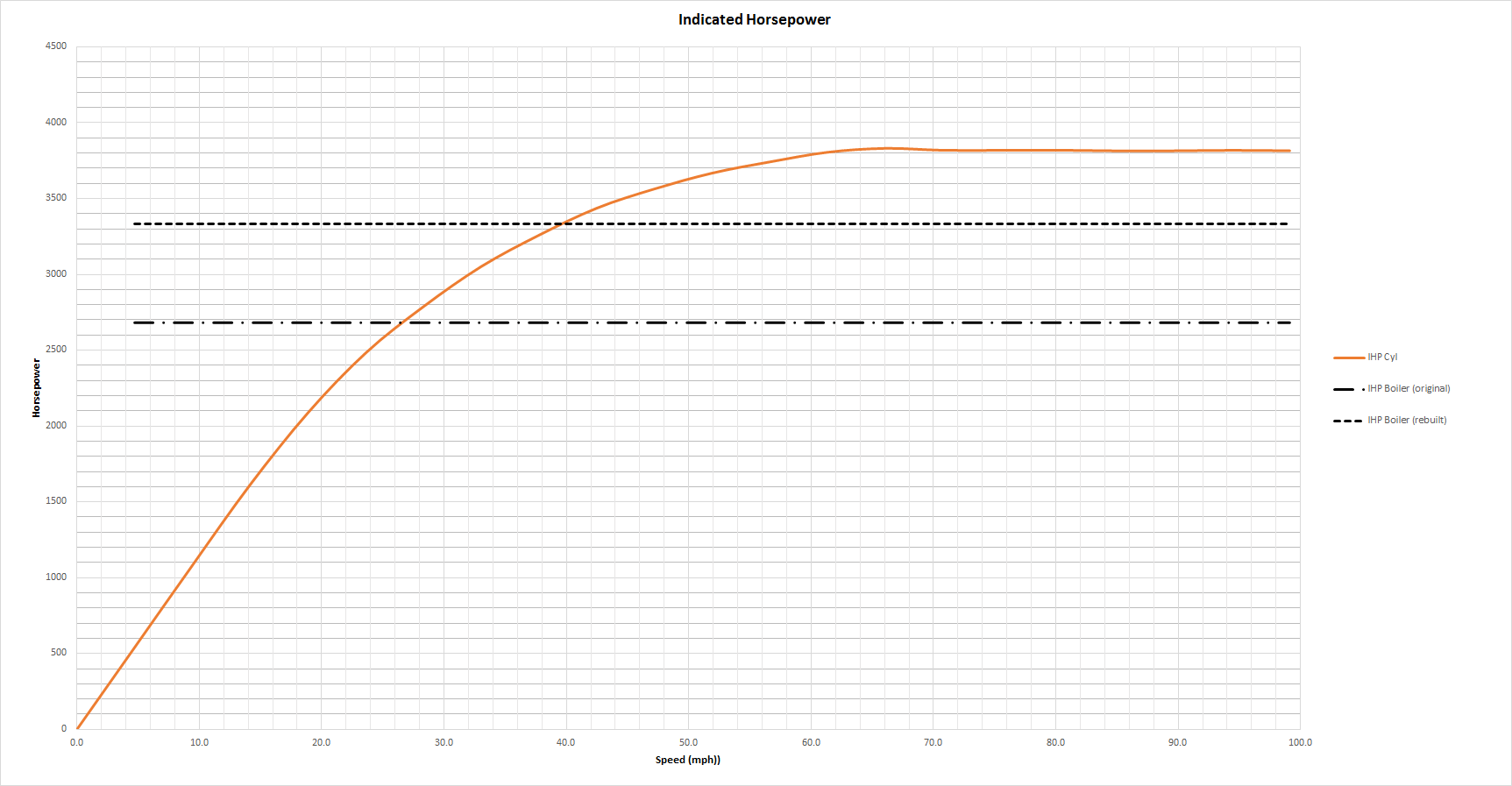
Indicated Horsepower is the theoretical power produced by the steam cylinder in a steam locomotive. On many locomotives the limiting horsepower is determined by the boiler steam generation capacity rather then the cylinder power (see below). The generally accepted formula for Indicated Horsepower is Where: Alternatively, using the formula above for tractive effort, the IHP can also be calculated by the following formula: Where: As shown in the diagram below, IHP increases with speed, until it reaches a maximum point. This maximum power value is either determined by the cylinders ability to maintain an efficient throughput of steam, or alternatively the boiler's ability to maintain sufficient steam generation to meet the steam usage by the cylinders. The lower of these two values will determine the power of the locomotive. For example in the diagram below for a sample locomotive, the cylinder indicated horsepower is shown by the orange curve, whereas the potential boiler horsepowers for the locomotive as originally built, and then later rebuilt are shown with black lines. Notice at low speed the cylinder horsepower is the limiting factor, until the cross over point is reached when the potential boiler power becomes the limiting factor. The diagram demonstrates that for the original locomotive, based upon the cylinder design parameters, the cylinder horsepower can reach values in excess of 3500hp. However the original boiler design and operation can only develop a maximum potential horsepower slightly in excess of 2600hp, thus the total power (maximum IHP) of the locomotive would only be in the order of 2600hp. However if the boiler can be rebuilt with better steam production capabilities and if it could potentially develop power in excess of 3300hp, then the total power (maximum IHP) would be limited at this higher value. The most famous demonstration of this concept in practice is provided by the British Railways Duke of Gloucester locomotive, which when originally built in the early 1950s developed a reputation as a "poor steamer", and subsequent offical testing the maximum IHP was determined to be in the order of 2500hp. The locomotive had a very short life in service due to dieselisation of the BR, but fortunately was eventually preserved, and during the rebuilding of the locomotive a number of design changes were made to improve the steam generation capabilies of the boiler. This resulted in the maximum IHP rising to values in excess of 3200hp. Thus whilst the cylinder horsepower didn't significantly change, the ability for the boiler to feed the cylinders increased thus increasing the maximum IHP of the locomitive. In his book (on page 150), Johnson, provides a method using common ratios to calculate the Potential Boiler Power which can be estimated by the following formula: Alternatively the following formula can be used to relate the boiler steam production to a quoted boiler horsepower value. Where: Fe = Factor of Evaporation = approx 1.0Indicated HorsePower (IHP)
IHP = Indicated Horsepowr (hp)
Cyl = number of cylinders
M.E.P. = mean effective pressure of cylinder (psi)
L = stroke of cylinder piston (ft)
A = area of cylinder (sq in)
N = number of cylinder piston strokes per min (NB: two piston strokes for every wheel revolution)
IHP = Indicated Horsepowr (hp)
TE = Tractive effort of locomotive (lbf)
S = Speed (mph)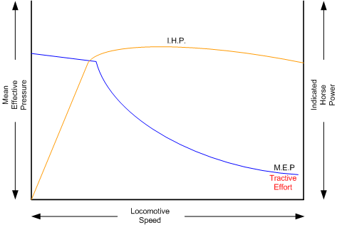
Drawbar Tractive Effort (DBTE)
Drawbar tractive effort is the pulling force exerted by the locomotive on the train behind it. With steam locomotives, the pull of the tender on the train is measured, usually with a dynamometer car, rather than the pull of the locomotive on the tender. It can also be calculated by measuring the tractive effort of the cylinder, and then subtracting the resistance force of the locomotive and tenderfrom it to determine the pulling power of the locomotive. Mathematically it is expressed as follows:
Where:
DBTE = Drawbar Tractive Effort (lbf)
TE = Tractive effort of locomotive (lbf)
Friction = Friction of lcocomotive and tender (lbf)
Note as the value of friction will vary depending upon whether the train is on a level track or going up or down a slope, etc, the DBTE will also vary accordingly. Similarly as TE varies (decreases) with speed so does the DBTE.
Drawbar HorsePower (DBHP)
DBHP, is horsepower calculated from draw bar pull and represents the power available to move and accelerate the train. Drawbar horsepower is usually measured by a dynamometer car coupled directly behind the locomotive, if no tender is attached, or behind the tender of a steam locomotive.
Where:
DBHP = Drawbar Tractive Effort (lbf)
DBTE = Drawbar Tractive effort of locomotive (lbf)
Friction = Friction of lcocomotive and tender (lbf)
Hauling Capacity of Locomotives
Thus it can be seen that the hauling capacity is determined by the summation of the tractive effort and the train resistance.
Different locomotives were designed to produce different values of tractive effort, and therefore the loads that they were able to haul would be determined by the track conditions, principally the ruling gradient for the section, and the load or train weight. Therefore most railway companies and locomotive manufacturers developed load tables for the different locomotives depending upon their theoretical tractive efforts.
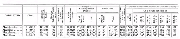
The table below is a sample showing the hauling capacity of a American (4-4-0) locomotive from the Baldwin Locomotive Company catalogue showing the relative loads on level track, and other grades, as the cylinder size, drive wheel diameter, and weight of the locomotive is varied.
Typically the ruling gradient is defined as the maximum uphill grade facing a train in a particular section of the route, and this grade would typically determine the maximum permissible load that the train could haul in this section. The permissible load would vary depending upon the direction of travel for the train.
Elements of Steam Locomotive Operation
The steam locomotive is a very complex piece of machinery that has many component parts, each of which will influence the performance of the locomotive in different ways. Even at the peak of its development in the middle of the 20th century, the locomotive designer only had at their disposal, a series of factors and simple formulae to describe its performance. Once designed and built the performance of the locomotive was measured and adjusted by empirical means, i.e. by testing and experimentation on the locomotive. Even locomotives within the same class could exhibit differences in performance.
For those interested in exploring this type of design information a bit further, then refer to the reference links below.
A simplified description of a steam locomotive is provided below to help understand some of the key basics of it operation.
As indicated above, the steam locomotive is a heat engine which converts fuel (coal, wood, oil, etc) to heat, this is then used to do work by driving the pistons to turn the wheels. The operation of a steam locomotive can be thought of in terms of the following broad components:
- Boiler and Fire (Heat conversion)
- Cylinder (Work done)
Boiler and Fire (Heat conversion)
The amount of work that a locomotive can do will be determined by the amount of steam that is able to be produced (evaporated) by the boiler. Boiler steam production is typically dependent upon the Grate Area, and the Boiler Evaporation Area.
Grate Area - the amount of heat energy released by the burning of the fuel is dependent upon the size of the grate area, draught of air flowing across the grate to support fuel combustion, fuel calorific value, and the amount of fuel that can be feed to the fire (a human fireman can only shovel so much coal in an hour). Some locomotives may have good sized grate areas, but were 'poor steamers' because they had small draught capabilities.
Boiler Evaporation Area - consisted of the part of the firebox in contact with the boiler and the heat tubes running through the boiler. This area determined the amount of heat that could be transferred to the water in the boiler. As a rule of thumb a boiler could produce approximately 12-15 lbs/h of steam for every sq ft of evaporation area.
Boiler Superheater Area - Typically modern steam locomotives are superheated, whereas older locomotives used only saturated steam. Suprheating is the process of putting more heat into the steam without changing the pressure. This provided more energy in the steam and allowed the locomotive to produce more work, but with a reduction in steam and fuel usage. In other words a superheated locomotive tended to be more efficient then a saturated locomotive.
Cylinder (Work done)
To drive the locomotive forward, steam was injected into the cylinder which pushed the piston backwards and forwards, and this in turn rotated the drive wheels of the locomotive. Typically the larger the drive wheels, the faster the locomotive was able to travel.
The faster the locomotive travelled, the more steam that was needed to drive the cylinders. The steam able to be produced by the boiler was typically limited to a finite value depending upon the design of the boiler. In addition the ability to inject and exhaust steam from the cylinder also tended to reach finite limits as well. These factor typically combined to place limits on the power of a locomotive depending upon the design factors used.
Steam Locomotive Types
During the course of their development, many different types of locomotives were developed, some of the more common categories are as follows:
- Simple - simple locomotives only had a single expansion cycle in the cylinder
- Compound - locomotives had multiple steam expansion cycles and typically had a high and low pressure cylinder.
- Saturated - steam was only just heated above the boiling point of water.
- Superheated - steam was heated well above the boiling point of water, and therefore was able to generate more work in the locomotive.
- Geared - locomotives were geared to increase the tractive effort produced by the locomotive, this however reduced the speed of operation of the locomotive.
Compounded Locomotives
One of the main causes of losses in the working of an ordinary (simple) engine was due to steam condensation which is set up when the steam at boiler pressure is brought into contact with the walls of a cylinder cooled down by the low temperature of the exhaust steam. One remedy is to superheat the steam before its arrival at the cylinder; another and older method is compounding.
In principle the highest steam locomotive efficiency can be obtained by compounding, and results in less steam and coal usage by comparison.. The steam is admitted into one cylinder called the 'high-pressure' cylinder, and expansion is allowed to commence therein, and afterwards it is exhausted into a second or 'low pressure' cylinder, where the expansion is continued. Thus a compound locomotive is considered to have two stages of expansion (one in each cylinder) compared to a simple locomotive. Most of the work is considered to be done in the low pressure cylinder. Compounding also produced a more even thrust on the connecting rods then a simple locomotive.
Many different types of compound locomotives have been designed over the years, and usually were grouped by the following characteristics:
- The number of cylinders employed.
- The location and character of the cylinders.
- The ratio between high- and low-pressure cylinder volumes.
- The number of axles directly driven from these cylinders.
- The arrangement, or not, of the cylinders, motion, and cranks to facilitate balancing.
- The provision, or not, of a receiver, and the ratio of receiver to cylinder volume.
- The relative angles at which the cranks are placed (for three or four-cylinder systems only).
- The employment of one slide or equivalent valve to control the steam distribution of each cylinder, or of each pair of cylinders, one high- and one low-pressure.
- The employment of two, three, or four sets of valve gear for two or four, three or four cylinders respectively, and the provision, or not, of means whereby the high- and low-pressure valve gears can be independently adjusted, or whereby the high-pressure valve gear can be adjusted while the low-pressure valve gear maintains a constant cut-off ratio.
- The nature and design of starting and intercepting valves.
- Automatic, the engine starting with boiler steam (generally at a reduced pressure) in the low-pressure cylinder or cylinders, and the valve or valves closing automatically as soon as the high-pressure exhaust attains sufficient pressure for working in the low-pressure cylinder or cylinders. The change from non-compound to compound working usually takes place after three or four strokes only, so that engines having valves of this class cannot be worked non-compound even temporarily. In fact, the principal reason for fitting starting and intercepting valves is to enable the engine to start with the low-pressure cylinder (in the case of a two-cylinder engine) when the high-pressure crank is on a dead centre.
- Under driver's control, so that the engine can be worked with boiler steam in the low-pressure cylinder or cylinders for as long as required at starting, or temporarily at other times.
- Combined automatic and under driver's control, automatic working resulting immediately after starting, unless the driver has manipulated a device whereby he can continue non-compound working.
- In several systems no starting valve, and sometimes no intercepting valve, is fitted, starting being provided for otherwise, or the engine being confined to compound working.
The most common types of compound locomotive are described here.
The use of superheated steam achieves similar outcomes to compounding, and was generally easier to implement due to the mechanical design and maintenance constraints, so it was more readily adopted compared to compounding. Often compound locomotives were trialed by railway companies, but they don't seem to have been adopted in large numbers.
Superheated Locomotives
In the early 1900s, superheaters were fitted to some locomotives. As the name was implied a superheater was designed to raise the steam temperature well above the normal saturated steam temperature. This had a number of benefits for locomotive engineers in that it eliminated condensation of the steam in the cylinder, thus reducing the amount of steam required to produce the same amount of work in the cylinders. This resulted in reduced water and coal consumption in the locomotive, and generally improved the efficiency of the locomotive. As superheating reduced the wire-drawing in the cylinder, it also increased the amount of work done in the steam cylinder, and thus the MEP of the locomotive was higher for the same relative speed, when compared to a locomotive without superheating fitted.
Superheating was achieved by installing a superheater element that effectively increased the heating area of the locomotive.
Geared Locomotives
Industrial type railways, such as those used in the logging industry, spurs to coal mines were often built to very cheap standards. As a consequence, depending upon the terrain, they were often laid with sharp curves and steep gradients compared to normal "main line standards".
Typical "main line" rod type locomotives couldn't be used on these lines due to long fixed wheelbase (coupled wheels) and their relatively low tractive effort were no match for the steep gradients. Thus geared locomotives found their niche in railway practice.
Geared locomotives typically used bogie wheelsets, which allowed the rigid wheelbase to be reduced compared to rod type locomotives, thus allowing the negotiation of tight curves. In addition the gearing allowed the increasing of their tractive effort to handle the steeper gradients compared to main line tracks.
Whilst the gearing allowed more tractive effort to be produced, it also meant that the "maximum" piston speed was reached at an earlier track speed. As suggested above, the maximum track would depend upon loads and track conditions. As these types of lines were lightly laid, excessive speeds could result in derailments, etc.
The three principal types of geared locomotives used were:
- Shay Locomotives
- Climax
- Heisler
Boiler Operation
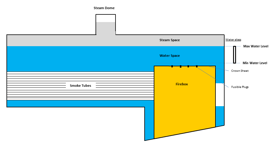
The key to a steam locomotives operation is the production of steam. The diagram below shows a cross sectional view of a typical steam locomotive boiler. Steam is produced by burning fuel in the firebox, which transfers heat to the water surrounding it in the boiler. And when the temperature of the water reaches boiling point steam is produced in the upper part of the boiler (Steam Space). Steam thus produced,is drawn off the top of the boiler via the Steam Dome, and piped to the steam cylinders to drive the steam pistons backwards and forwards to produce movement of the locomotive wheels.
To protect the firebox of the locomotive from overheating a number of fusible plugs are incorporated into the crown sheet of the firebox. If the water level in the boiler drops to near the firebox crownsheet, then the fusible plugs are designed to melt and allow water to enter the firebox to extinguish the fire, and protect the friebox from damage. Thus when driving, the fireman must ensure that the boiler water level does not drop below a safe coverage distance over the firebox. Similarly, he musn't overfill the boiler with water as this will reduce the amount of steam available to the steam pistons, and in extreme cases will cause the locomotive to 'prime' (i.e., where water is forced out of the boiler into the steam pistons, causing severe dmagae to the pistons).
In most locomotives, two water glasses are provided in the cabin to show the fireman the current water level in the boiler. The water level in the boiler should be maintained between the top and bottom limits of the water glass. Typically the lower limit of the water glass is approximately at the 70% water mark of the boiler, and the top limit, where the steam space starts, is at approximately 90%.
Boiler Blowdown
As water is evaporated in the boiler to create steam, any soluble salts, such as calcium and magnesium salts become insoluble due to the increased boiler temperatures and pressure. Some of these salts fall on hot surfaces where they bake and form a scale while other salts sink to the bottom of the boiler as sludge. To maintain the efficiency of the boiler it is necessary to remove this sludge on a regular basis. Hence the quality of watering points was sometimes an issue for railway companies. Depending upon the water quality crew may need to blow down quite regularly, in extreme cases this could be a number of times within a 100 mile operation.
To facilitate this, a blowdown valve was fitted to the bottom of the boiler which allowed a mixture of water and the sludge to be removed from the boiler. This process was either a manual operation undertaken by the crew at opertune times, or alternatively an automated process which occurred as the locomotive was moving. As the water was drawn from the boiler, it often would create flash steam. This could provide quite a spectacular view when the locomotive crew operated the blowdown valve, as shown in the following video.
Operation of the blowdown valve will reduce the amount of water in the boiler as well as the stored heat in the boiler, so it is a process that was not undertaken for long periods of time. Typically automatic blowdown systems drew off less amounts of water, and hence didn't disturb the boiler heat balences as much. As can be seen from the video, the resulting steam could cause injuries to the crew or passengers, so the crew needed to be careful when they undertook a blowdown operation.
To set up the boiler blowdown function in OR, see the description in the Boiler Blowdown section.
Boiler Insulation
In order to maintain the highest level of boiler efficiency locomotive design engineers insulated (or "lagged") the boiler to reduce heat losses. The earliest steam locomotives used strips of wood grooved on each side, fitted around the boiler, and held together with wooden hoops. This design was similar in construction to a wooden barrel. However as newer designs produced higher temperatures, and pressures wooden insulation was found to be an unsatisfatory material to use as a boiler insulation. Improved insulating methods included applying a thick paste containing a porous mineral such as kieselgur, or attaching shaped blocks of insulating compound such as magnesia blocks. In the latter days of steam, "mattresses" of stitched asbestos cloth stuffed with asbestos fibre were fixed to the boiler, on separators so as not quite to touch the boiler. However, asbestos is currently banned in most countries for health reasons. The most common modern-day material is glass wool, or wrappings of aluminium foil. The lagging is protected by a close-fitted sheet-metal casing known as boiler clothing or cladding.
The main factors effecting the amount of heat loss are as follows:
- Boiler Surface Area - Large surface areas exposed to the elements will result in larger heat losses then smaller surface areas.
- Insulation Type - The type of insulation will also impact heat losses as some materials are better insulators the others. Typically K value, or coefficient of thermal conductivity will demonstrate this difference.
- Level of Insulation - It was not possible to apply insulator to the complete boiler surface area, and hence areas that were not covered lost more heat then areas covered by insulation. Hence the proportion of the boiler insulated can result in different levels of heat loss.
- Temperature Difference - The difference in temperature between the water in the boiler and the ambient temperature. Movement of the locomotive will also result in a higher temperature differece as the "wind chill" is a factor.
Steam Cylinder Indicator Diagram - Single Expansion (Simple) Locomotive
To measure the performance of a steam locomotive an indicator diagram was produuced. The "indicator" was an instrument that was attached to the locomotive steam cylnder, and produced a graph showing the cylinder movement (change in volume) compared to the varying pressures in the cylinder. The shape of this graph assisted the designer in assessing the locomotive performance. Many factors, including the valve gear operation, etc would influence the shape and key points on the graph.
The diagram below represents a typical indicator diagram, with the vertical axis representing the pressure in the cylinder, and the horizontal axis representing the stroke (volume) in the cylinder. This diagram was used to calculate key performance characteristics of the locomotive, including the amount of work done by the steam, and potential losses in efficiency.

In the graph above the area shaded green represents the amount of work that is done by the steam. The area shaded red represents losses in efficiency throughout the cycle, compared to an "ideal" steam locomotive cylinder. Over the years, locomotive designers would study the red areas and implement design features to reduce the size of these areas, and attempt to convert them to green shading, effectively increasing the work done by the steam, thus increasing the efficiency of operation of the locomotive.
The red areas marked with the following areas represent opportunities for the locomotive designers to improve the efficiency as follows. Some of these areas can be modified by entering configuration parameters via the ENG file. For more details refer to this Advanced Steam Settings page.
- A - this represents the loss of efficiency due to intial pressure drop and cutoff pressure drop.
- B - this represents the loss of efficency due to the timing of the opening of the exahuast value.
- C - this represents the loss of efficency due to the back pressure in the cylinder.
- D - this represents the loss of efficency due to the compression within the cylinder.
This diagram was typically considered in two "halves", one representing the forward movement of the steam piston (positive stroke), and the other representing the return movement of the piston (negative stroke). The diagrams below represent these two respective "halves".
Key Features on Indicator Diagram
Vacuum line - is the base axis, and represents the line of perfect vacuum, or no pressure (ie 0 psi).
Atmospheric pressure line - Atmospheric pressure at approximately 14.7 psi above the Vaccum line. Typically steam gauges on locomotive measure "gauge" pressure, rather then atmospheric pressure. Thus there is a difference of 14.7 psi between the pressure reading seen on the locomotive negineers pressure gauge and atmospheric pressure. For example, a locomotive with a 200 psi boiler pressure, would actually have a boiler pressure of 214.7 psi above atmosphere. All pressure associated with the steam cylinder indicator diagram are measured in atmospheric pressures.
Boiler pressure line - is the rated working pressure of the boiler.
Steam Chest pressure line - during the stroke of the cylinder steam was initially admitted to the steam chest, before being injected into the steam cylinder. The steam chest pressure represents the pressure of the steam in the steam chest compared to the boiler pressure. It will be noted that this line is slightly lower then the boiler pressure, and represents the impact of the friction encountered by the steam as it passes through the various valves and pipes to get to the steam chest.
Clearance - the space between the piston at the end of its stroke and the valve-face. It is usually reckoned in per-cent or fraction of the piston-displacement, or in its equivalent in length added to the cylinder.
Positive (Forward) Stroke
The forward stroke of the steam piston is where all the work is done to convert steam heat energy into the mechanical force to drive the wheels. Thus this portion of the stroke is considered to have a "positive" effect on force generation. The stroke can be broken into the three stages of admission, expansion, and release.
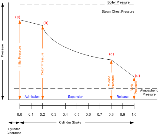
The respective pressure values in this half of the steam indicator diagram are:
- a - Initial pressure
- b - Cutoff pressure
- c - Release pressure
- d - Back pressure
Admission stage - At the commencement of the stroke (a), steam is admitted to the cylinder until the cutoff point (b) is reached, at which time further steam is preventing from entering the cylinder. When starting the locomotive, the cutoff point will be typically extend for longer portions of the cylinder stroke, whereas whilst running at speed small values of cutoff will be used by the driver. On our graph the line between the Initial and Cutoff pressure points (a - b) represents the admission phase. Whilst ideally this line should be parallel to the steam chest pressure line, it in fact decreases until the cutoff point is reached. The reduction in cutoff pressure is due to the ability of the cylinder to accept steam, and will decrease as the speed of the locomotive increases.
Expansion stage - Once the steam valve is closed at the end of the admission stage, the steam will expand to continue pushing the steam piston to the end of its stroke. This is called the expansion stage.
Release stage - once the steam has expanded and pushed the piston towards the end of it stroke (d), the steam valves will open to allow the steam to be released (c) or exhausted from the cylinder. This is known as the release stage.
Negative (Return) Stroke
Once the cylinder piston reaches the end of its forward stroke (d), it commences the return stroke. This is shown on the "negative" section of the indicator diagram below. It also can be broken into three stages consisting of Exhaust, Compression and Pre-admission.
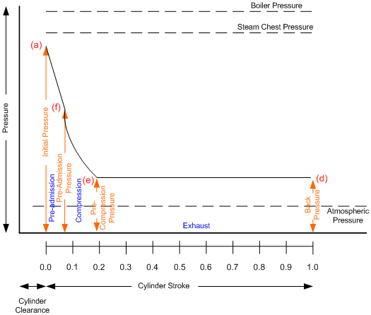
The respective pressure values around the steam indicator diagram, as reported by Open Rails are:
- a - Initial pressure
- d - Back pressure
- e - Pre-compression pressure
- f - Pre-admission pressure
Exhaust stage - during the early stages of the piston return stroke, steam is exhausted out of the cylinder. Locomotive designers have strived to reduce the value of back pressure to as small a value as possible. Typically the back pressure is impacted by the size of cylinder port openings, etc.
Compression stage - eventually in preparation for the next stroke the steam valve is closed (e), and no more steam is exhausted from the cylinder. Typically there is still some steam left in the cylinder, so consequently the piston compresses this steam as it continues on its return stroke. This compression is also a negative influence on the work done by the cylinder, and also special attention is paid by locomotive designers.
Pre-admission stage - As the piston reaches the end of its return stroke the valves open again (f) to allow steam to be injected into the cylinder for the next stroke, and hence the cycle starts again.
Steam Cylinder Indicator Diagram - Double Expansion (Compound) Locomotive
There were a large variety of compound locomotives developed over the years as designers experimented with different features. Open Rails, at this time, only models the non-receiver Vauclain 4 cylinder type of locomotive. Similarto above the steam indicator diagram is used to calculate the MEP and steam consumption of the locomotive.
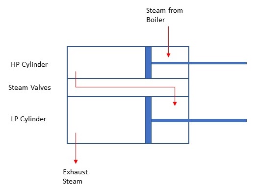
In the Vuclain compound locomotive the steam cylinders were arranged as shown in the diagram below. In studying the diagram it can be seen that the cylinders pistons were positioned so that they were at the same relative position as each other, and steam was injected into the HP cylinder which pushed the steam piston forward and at the same time steam was exhausted from the HP to LP cylinder. This resulted in the LP cylinder being also pusehed forward by this this exhaust steam.
Non-receiver type steam indicator diagram.
The principles used to identify work done, losses, and calculate steam pressures, etc, are similar to the simple (single expansion) indicator diagram, so only features relevant to the following diagram will be described below.
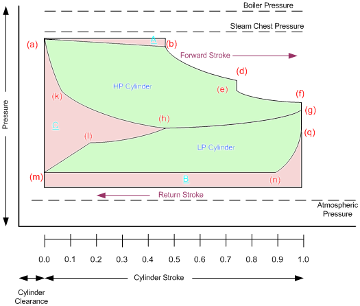
This type of steam engine was also known as the Woolf or "continuous expansion" type engine. The enclosed green area at the top of the diagram represents the work done by the HP cylinder, whilst the lower green area represents the LP cylinder.
The respective pressure values around the steam indicator diagram are:
- a - HP Initial pressure
- b - HP Cutoff pressure
- d - HP Release pressure
- e - HP Release pressure (with Connecting steam passages)
- f - HP Exhaust pressure
- g - LP Initial pressure
- h - LP Cutoff pressure
- k - HP Pre-admission pressure
- l - LP Release pressure
- m - LP Back pressure
- n - LP Pre-compression pressure
- q - LP Pre-admission pressure
Referencing the points around the diagram:
HP Admission - Started at (a) and continued until cutoff at (b).
HP Expansion - Started at (b) and continued until release at (d).
HP Exhaust - Started at (e) and continued until release at (f). The drop in pressure at (e) was due to the steam filling the passages between the two cylinders.
LP Admission - At (f) LP steam valve opened and allowed steam to flow into the LP cylinder, and there was another drop in pressure to (g). From (g - h) the HP and LP cylider were connected together until (h) was reached when the LP steam valve closed. The resulting steam in the HP then was compressed as the HP cylinder completed its cycle, whilst the newly injected steam in the LP cylinder expanded.
LP Expansion - Started at (h) and continued until release at (l).
LP Exhaust - Started at (l) and continued until (m).
HP Pre-compression - Started at (h) and continued until (k) as the steam in the HP cylinder and the connecting passages was compressed.
HP Compression - At (k) the HP exhaust valve closed and the steam in the HP Cylinder was compressed further until the piston reached (a).
LP Pre-compression - Started at (m) and continued until (n) as the steam in the LP cylinder was exhausted.
LP Compression - At (n) the LP exhaust valve closed and the steam in the LP Cylinder was compressed further until the piston reached (q).
Indicator Diagram Interpretation
The Indicator diagram can be used to calculate some of the key operational characteristics of the steam locomotive as follows:
Mean Effective Pressure (M.E.P.)
The MEP is a measure of the work done by the steam in the cylinder. It is described by the following formula:
Work done by Cylinder = Work done on positive Stroke - Work losses on negative stroke
Positive work can be calculated by finding the area under the curve in the forward cylinder stroke and Negative work is calculated by finding the area under the curve for the return cylinder stroke.
The M.E.P. is then used to calculate the locomotive tractive effort and Indicated Horsepower.
Steam Cylinder Consumption
The amount of steam in the steam cylinder at any point in the stroke can be measured from the indicator diagram, but unfortunately the water present (due to condensation) that entered the cylinder as steam cannot be so measured. Thus the steam cylinder indicator diagram cannot provide the actual steam consumption of the locomotive, but it gives us an approximation of the steam consumption. A multiplication factor can be applied to allow for steam condensation in the cylinder.
To measure the steam consumption according to the indicator, a point in the stroke just previous to the opening of the exhaust-valve is selected. The displacement of the piston in cubic feet up to that point, plus the clearance-space, multiplied by the weight of a cubic foot of steam of the pressure at the point selected, will give the weight of steam present. From this must be deducted the steam saved by the closing of the exhaust-valve before the end of the stroke, the remainder being the steam expended. Instead of determining the steam used per stroke, it is better to calculate the amount used per hour.
Steam Locomotive Booster Engine
The steam locomotive booster engine was a small 2-cylinder geared engine that could be used to provide additional tractive effort at low speeds. The typical locomotive booster employed a pair of 10-inch-bore (250 mm) by 12-inch-stroke (300 mm) cylinders, and generally drove the rear trailing axle(s) of the locomotive, although some boosters drove tender axles. They were designed to improve the starting acceleration of heavily loaded trains.
Boosters had a fixed gear ratio and worked at a fixed cut-off. They were controlled by compressed air and were intended to be used when the locomotive was operating at low speeds with long cut-offs. When the driver reduced the cut-off setting of the main engine the booster would automatically be disengaged. Boosters could only be used in the forward direction.
The following picture from The Locomotive Booster Instruction by Franklin Railway Company and shows the basic components of the Booster Engine.
Boosters were used on a number of large locomotives in USA. They were also applied to a few locomotives in Australia, New Zealand and UK, but with limited success.
The idea of the booster was proposed by Howard L. Igersoll of the New York Central Railway. The first booster, manufactured by the Franklin Railway Supply Company being put into use in 1919 on New York Central Railway Atlantic locomotive number 990. The design of the booster was patented and developed by Franklin also sold their products under the name of the "Locomotive Booster Company".
At high speeds the power of a steam locomotive is generally limited by the ability of the boiler to produce sufficient steam to drive the cylinders. At low speeds on the other hand the boiler is able to generate a much larger amount of steam than can be used in the engine. The booster allows more of this steam to be used. Since the booster engine drives axles that would normally be unpowered, then it effectively increases the adhesive mass (and factor of adhesion) as well as the tractive force available. In publicity materials the Franklin Railway Supply Company advertised, "The Locomotive Booster makes it possible to use more of the weight of the locomotive on the rails to produce power".
Booster engines on trailing trucks drove one axle only of the trailing truck. Boosters used underneath tenders usually had two axles coupled together by a coupling rod so that both were driven. The A.A.R. formula for the tractive force developed by a booster was given in the Railway Mechanical Engineer (1942, July, p321) as:
where
T = tractive force lb
C = ratio of MEP in cylinder to boiler pressure and is 0.80 for 75% cut off booster, 0.774 for 70% cut off booster, 0.73 for 50% cut off booster
P = boiler pressure in PSI
d = diameter of cylinder in inches
S = stroke of piston in inches
D = diameter of booster driving wheels in inches
r = booster gear ratio
Specifications of the most widely used booster engines are given below.
Some readily available gear ratios and associated operating speeds for both the Franklin type C and type E booster models are detailed in the table below.
|
Gear Ratio |
Max Cut-in Speed. |
Max. Operating Speed. |
|---|---|---|---|
Franklin Type C-1 and C-2 |
2.571 |
12 mph (19 km/h) |
21 mph (34 km/h) |
Franklin Type E and E-1 |
2.71 |
15 mph (24 km/h) |
25 mph (40 km/h) |
2.25 |
18.5 mph (29.8 km/h) |
30 mph (48 km/h) |
|
2.00 |
22 mph (35 km/h) |
35 mph (56 km/h) |
Operational Notes
- The booster should only be operated when the locomotive is moving forwards, or starting from rest in the forward direction.
- The booster should not be engaged if speed is greater than the maximum engagement speed for the model of booster.
- The booster must be disengaged before the train reaches the maximum operating speed for the model of booster. (This is usually achieved by reducing the cut-off of the main engine.)
- The booster must be disengaged before bringing the train to a halt.
- Whenever possible the booster should be operated in "idle" mode for at least two minutes before being placed into "running" mode.
To set up the booster engine function in OR, see the description in the Booster Steam Engine section.