Route Building Parameters

Aim - this pages describes some of the special features that are available in Open Rails, and how to set them up within Open Rails.

If you wish to provide any feedback on this page, please use the contact page. It would be great to have some feedback as this helps to ensure the accuracy of the information and models.

Index

Introduction

Pickup Points for Loads and Refueling

Turntable Animation

Car Spawners

Tree Clearing

Tunnel Resistance Parameters

Track SuperElevation

Route Related Sounds

Analogue Station Clocks

Grade or Level Crossing Placement with TSRE

Creating a Track Crossover

Key Open Rails Parameters for Route Building

Useful References


Introduction

To enhance its realism and performance a number of new features and functions have been added to Open Rails. The features described on this page are those elements that are implemented or activated as part of the route design or specification. In some instances the features will also require parameters to be set in the ENG or WAG files to ensure full functionality of the feature or function.

The following features are described here:

  • Creating Operational Turntables
  • Clearing Trees from tracks
  • Tunnel Resistance Parameters
  • Track SuperElevation
  • Analogue Station Clocks
  • Grade or Level Crossings

To implement these features additional information needs to be inserted into various files as described in the relevant section. However making changes directly to these files may be overrriden by MSTS when editing the route in MSTS Routre Editor (RE), or alternatively it may cause instability issues with MSTS, so a method to include the information has been devised that doesn't require the direct editing of these two files directly. Instead an 'include' file is created with the data to be read by Open Rails. These files are created and stored in a sub-folder placed directly under the root folder of the route.

The structure of these files for each feature will be described in more detail below, and a working example of these files can be found in the Coals to Newcastle test route.

top


Pickup Points for Loads and Refueling

Open Rails currently supports the following pickup points for loading/unloading and refueling:

  • Null (Type = 0)
  • Freight - Grain (Type = 1)
  • Freight - Coal (Type = 2)
  • Freight - Gravel (Type = 3)
  • Freight - Sand (Type = 4)
  • Fuel - Water (Type = 5)
  • Fuel - Coal (Type = 6)
  • Fuel - Diesel (Type = 7)
  • Fuel - Wood (Type = 8) (NB - This is not an option in MSTS)
  • Fuel - Sand (Type = 9) (NB - This is not an option in MSTS)
  • Freight - General (Type = 10) (NB - This is not an option in MSTS)
  • Freight - Livestock (Type = 11) (NB - This is not an option in MSTS)
  • Freight - Fuel (Type = 12) (NB - This is not an option in MSTS)
  • Freight - Milk (Type = 13) (NB - This is not an option in MSTS)
  • Special - Mail (Type = 14) (NB - This is not an option in MSTS)

Pickup points can be animated so that they move into position to fill the wagon or locomotive.

To implement a pickup point use the RE to insert a pickup point, if the load type is not one of the standard load types, then the W file can be edit with a unicode text editor, or alternatively a standard default point can be inserted, and then overwritten with an INC file as described in the section below.

Changing Pickup Point Type

The pickup point's type is defined in world files using the parameter PickupType ( 6 1 ), where the first number in the brackets relates to the type number as defined in the list above. This number can either be edited using the MSTS Route Editor, or alternatively using a unicode text editor in the relvant world file.

Changing Pickup Point Load or Unload

To distinguish between a loading or unloading point it is necessary to set the Fill Rate value as positive for a loading point, and negative for an unloading point. This number can either be edited using the MSTS Route Editor, or alternatively using a unicode text editor in the relvant world file. For example, the second number in the PickupCapacity ( 200000 2000 ) parameter is the fill rate, by setting it to a negative value, the "pickup point" will be recognised as an unloading point. For example, PickupCapacity ( 200000 -2000 ).

INCLUDE File to Overwrite Default MSTS code

As some of the above load types are not defined in MSTS, when using MSTS RE it is not possible to select any of the load types with a value greater then 7, instead they need to be manually edited in the W file. There is also a risk when editing the file in MSTS that they could default to a different load type, so it is suggested that an INCLUDE file is used to overwrite the relevant code in the W file.

SIMISA@@@@@@@@@@JINX0w0t______

Tr_Worldfile (

Pickup (
    UiD ( 70 )
    SpeedRange ( 0 2 )       Comment ( Freight - Fuel Loading Point )
    PickupType ( 12 0 )
    PickupAnimData ( 3 0 )
    PickupCapacity ( 1e+006 5000 )
)

Code Notes:

  • UiD ( x ) - must match the pickup point that is being overwritten by this code segment.
  • SpeedRange ( x y ) - sets the speed range for the train when using the pickup point. x = minimum speed, y = maximum speed. Units m/s.
  • PickupType ( x y ) - sets the pickup type. x = load type, a number from the above table. y = "never runs out", 0 = capacity specified in dialog box, 1 = infinite
  • PickupCapacity ( x y ) - sets the capacity of the pickup point. x = capacity in lbs per quantity. y = fill rate in lbs/s. (+ve for loading point, -ve for unlaoding point).

These types of code segments are included in a file named the same as the file in which they will replace the default code in, ie w+xxxxxx+yyyyyyy.w. These files are grouped within the OpenRails folder within the W folder. Mulitple pickup point code segments can be included in each W file thus defined. For a demonstration refer to w+001497+010303.w in the OpenRails folder within the W folder of the CTN Test Route.

If the W is edited in MSTS RE, check that the UiD identification numbers still match the code segments described above.

top


Turntable Animation

Introduction

Open Rails supports animation of turntables under two different scenarios:

  • TSection - If a turntable is defined within the TSECTION file, such as the default turntable a1t27mturntable.s found within MSTS, then it can be automated to rotate.
  • Static - If a turntable has been created as a static object only, then it maybe possible to convert it to an animated one. In this scenario it is effectively converted to a trackpiece that can be imported into a route.

The steps to implement an animated turnatble are as described below. Both the TSection and Static model follow a similar set of basic steps, except where indicated:

  • Step 1 - Modify the turntable S file to support animation
  • Step 2 - In the case of the static scenario, TSection elements will need to be incorporated into it the route. The TSection type turntable should already be defined
  • Step 3 - Place the turntable in the relevant location with the Route Editor tool. For the static turntable scenario, this will modify the W file to change the turntable from a static object to a track object.
  • Step 4 - Create a turntables.dat file to provide details on the location of operational turntables within the route.
  • Step 5 - Add sound effects to the turntable as appropriate.

A working example, using the default MSTS 27m turntable and a static 60ft model, has been provided in the Coals to Newcastle Test route. The working turntables can be found on tile 1493, 10308. The following description uses these as the basis for describing the setup of the two different types of turntables.

Step 1 - Turntable S File Animation

The turntable S file must contain an appropriate hierarchy structure separating the turntable bridge (part that rotates) from the turntable base (part that remains stationary). Shape Viewer can be used to confirm this hierarchy structure. For example, in the following screenshot from Shape Viewer, 'Deck' represent the model parts that will rotate when the turntable is animate, whilst 'Foundations' are all the remaining parts that are stationary.
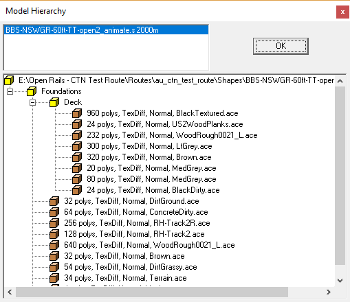
Turntable hierarchy

To animate the turntable, uncompress the shape file, and insert the following code into the S file prior to the last parenthesis (or bracket) in the file. Note the use of the 'Deck' name as part of the anim_node, and the need to ensure that all parenthesis are included.


animations ( 1
    animation ( 3599 30
       anim_nodes ( 2
          anim_node Foundations (
             controllers ( 0 )
          )
          anim_node Deck (
             controllers ( 1
                tcb_rot ( 5
                  slerp_rot ( 0 0 0 0 1 )
                  slerp_rot ( 900 0 0.7071068 0 0.7071067 )
                  slerp_rot ( 1800 0 1 0 -1.629207E-07 )
                  slerp_rot ( 2700 0 -0.7071066 0 0.7071069 )
                  slerp_rot ( 3600 0 0 0 1 )
             )
           )
         )
       )
     )
  )

Once the modifications are complete, then the S file should be inserted into Global\Shapes folder so that OR can access it.

More Info

Note the animation code must be modelled such that it causes the turntable to rotate in a counter clockwise direction.

Step 2 - Create TSection Entries

As the turntables are effectively tracksections, they will need to be already defined in the TSection file (in the case of existing turntables), or alternatively able to be imported into the trackdatabase at runtime of Open Rails (in the case of static turntables). For our example the 27m turntable is already defined in the TSection file, so we can skip this step for it. However the 60ft one is not defined in the TSection, so it will need to have the relevant SectionIdx entries generated for it. The following code section demonstrates the type of entries required for the tsection.dat file that needs to be included in the Open Rails sub-folder.

include ( "../../../Global/tsection.dat" )
_INFO ( Track section and shape addition for turntable BBS-NSWGR-60ft-TT-open2_animate.s )
   TrackSections ( 40000
_SKIP ( Track section for turntable BBS-NSWGR-60ft-TT-open2_animate.s )
      TrackSection ( 37298
       SectionSize ( 1.5 18.6 )
   )
   )
   TrackShapes ( 40000
_INFO(TrackShape for turntable BBS-NSWGR-60ft-TT-open2_animate.s)
      TrackShape ( 37298
      FileName ( BBS-NSWGR-60ft-TT-open2_animate.s )
      NumPaths ( 3 )
      SectionIdx ( 1 0 1.35 -9.300 0 37298 )
      SectionIdx ( 1 -9.300 1.35 0 90 37298 )
      SectionIdx ( 1 6.576, 1.35, -6.576 -45 37298 )
   )
   )

Code Notes:

  • The first line must be blank
  • The second line has an include statement to indicate which file that this information needs to be added to.

  • TrackSections - is the number of track pieces defined in the TSection file. Typically this will not need to modified.
  • TrackSection - is the reference number that we will allocate to our track piece (turntable). This will be used in the W file as reference. Note this number should be unique, and not one that is already in use.
  • SectionSize - describes the gauge and length of the section that we are defining. Note MSTS default gauge is 1.5.
  • TrackShape - the same number as the trackshape number.
  • FileName - the name of the S file. Note that as this is a track section now, it must be located in the Global shapes folder.
  • NumPaths - the number of possible paths on the shape.
  • SectionIdx - ( n x y z d s1 s2 ... sn) : each SectionIdx describes a path within this TrackShape. n is the number of s-values to expect. x, y, z is where the path starts relative to the shapes origin. d is the initial direction of the path with 0 being straight on, minus values to the left and plus values to the right. s* is a reference to a TrackSection, the path is built by adding these TrackSections to each other in the order stated.

To ensure correct operation of the turntable, the SectionIdx entries need to be referenced to the object reference point. The diagram below demonstrates the referencing of the key points as used in the 60ft turntable. The Object reference point is in this case in the centre of the object. The turntable has three paths defined, as shown by the blue lines.
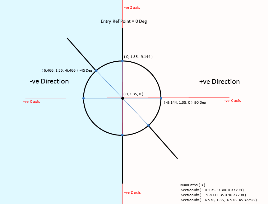
SectionIDX Co-ordinates

Drawing notes:

A tool to determine the relevant entries for the SectionIDX values is available for use. Simply enter the diameter of the turntable and the degree steps between the track sections to get the correct entries. Whilst this tool may generate multiple paths, depending upon the separation degrees choosen, any number of paths can be defined in the SectionIDX entries.

In the case of our turntable, in the tool, choose a value of 18.6 (approx 60m) for the diameter, and, as we want at least one path at 45 degrees, an Angle setting of 45 deg. It may be necessary to adjust the diameter value slightly as this will determine where the entry and exit tracks will attach to the turntable.

Description of paths used in the 60 ft turntable:

For a static turntables, to use MSTS RE, it will be necessary to temporarily insert the TSection information defined above into the main MSTS TSection file. This will allow selection and editing as a track piece, and will also ensure that it is correctly defined in the W file. When viewed in Route Editor, it should show relevant blue poles for track connections. Note if you wish to change the TSection settings for your turntable, always delete it from the route first before using the RE to insert it int the route. Failure to do this may cause issues with the track database, and result in opening faults.

Once you have defined your TSection entries, then use the information to create the tsection.dat file for distribution with OR routes.

Step 3 - Turntable Installation and World File Adjustment

By this stage you should be able to insert the animated turntable into the correct location in the world file using the Route Editor tool.

Once the turntable is correctly placed, it will usually appear as a TrackObject in the relevant world file, as shown below. Some of this information will be required to define the turntable location as described in the next step.

TrackObj (
    UiD ( 124 )
    SectionIdx ( 37298 )
    Elevation ( 0 )
    CollideFlags ( 23 )
    FileName ( BBS-NSWGR-60ft-TT-open2_animate.s )
    StaticFlags ( 00200180 )
    Position ( 172.979 -0.35 418.047 )
    QDirection ( 0 -0.422616 0 0.906309 )
    VDbId ( 4294967294 )
)

If the turntable is already defined in the TSection file, then placing the turntable in the route will merely be a case of using MSTS RE (OR route editor) to place the turntable and track around it.

Step 4 - Turntable Location

A special file called turntables.dat is defined within the Open Rails folder in the Route folder. This file has the following code structure:
2
Turntable(
WFile ( "w+001493+010308.w" )
UiD ( 86 )
XOffset ( 0 )
YOffset ( -1.92177 )
ZOffset ( 13.4 )
TrackShapeIndex ( 253 )
Animation ( "TRACKPIECE" )
Diameter ( 27 )
)
Turntable(
WFile ( "w+001493+010308.w" )
UiD ( 124 )
XOffset ( 0 )
YOffset ( 1.35 )
ZOffset ( 0 )
TrackShapeIndex ( 37298 )
Animation ( "Deck" )
Diameter ( 18.6 )
)

Code Notes:

  • The first line must be blank
  • The second line contains a number indicating the number of operational turntables in the route, and hence included in this file.
  • Wfile - the name of the W (world) file in which the turntable is located.
  • UID - the UID of the object within the W (world) file. If there is more then one operational turnatble on a tile, then this number will differentiate between them.
  • XOffset, YOffset, ZOffset - are the offsets of the center of rotation of the turntable with respect to the zero of the turntable shape. These may need to be adjusted by trial and error, in particular the height (Y) offset may require adjusting to match track heights.
  • TrackShapeIndex - the number of the SectionIdx from the W (world) file, which should correspond to a Trackshape number in the TSection file. In the case of the defualt MSTS 27m turntable, it was already defined within the TSection file, wheras the static turntable doesn't have a TSection entry.
  • Animation - the name of the moving parts from the hierarchy structure of the S file.
  • Diameter - the diameter of the turntable in metres.

Step 5 - Turntable Sounds

To add sounds to the turntable, add the following statement to the route TRK file in the Open Rails sub-folder.

Comment ( Adds sounds for turntables )
   ORTSDefaultTurntableSMS ( turntable.sms )
Turntable Operation

To test your turntable, run your train over it. If it is working correctly then messages should appear indicating the the train is moving onto the turntable. If you don't get these messages, then check your settings above.

Once you are successfully on the turntable, then ensure that the locomotive is in neutral, throttle is off, and speed is zero. Then press the Alt-C key to rotate in a clockwise direction, or Ctrl-C to rotate in an anticlockwise direction.

The above steps must be repeated for every route where you want to have operational turntables

top


Car Spawners

Multiple car spawners can now be used in Open Rails so that different traffic patterns can be used on different road sections.

The use of multiple car spawners is demonstrated in the Coals to Newcastle test route on tile 1493, 10307.

The steps to implement multiple carspawners are as described below:

Step 1 - Insert Car Spawners into Route

Using a n appropriate editing tool insert car spawners at the locations required. For the time being these will use the car spawner lists defined by default in the carspawn.dat in the root Route folder.

Step 2 - Create Additional Car Spawner Lists

In this step we create the additional non-default lists of cars that we wish to use in our Route. These lists use the code format shown below and should be in saved in a file called, carspawn.dat, stored in the OpenRails folder under the root Route folder.

SIMISA@@@@@@@@@@JINX0v1t______

2
CarSpawnerList(
   ListName ( "List1" )
      1
      CarSpawnerItem( "Jp1Car01.s" 4 )
)
CarSpawnerList(
   ListName ( "List2" )
      1
      CarSpawnerItem( "OL_Flatbed_Drums.s" 6 )
)

Code Notes:

  • The third line contains a number indicating the number of different carspawner lists used in the route, and hence included in this file.

  • ListName - is the name of the carspawner list.
  • The sixth line contains a number indicating the number of different vehicles defined in the carspawner list.
  • CarSpawnerList - defines each vehicle used in the list. The first item is the shape file of the vehicle, and the number indicates the spacing between the vehicles.

Step 3 - Create References to Additional Car Spawner Lists

In this step we create the references to the additional non-default lists of cars that we wish to use in our Route. These lists use the code format shown below and should be in saved in a file called, w+001493+010307.w, stored in the OpenRails folder under the World folder in the Route.

SIMISA@@@@@@@@@@JINX0w0t______

Tr_Worldfile (
    CarSpawner (
       UiD ( 32 )
       ORTSListName ( "List1" )
    )
    CarSpawner (
       UiD ( 31 )
       ORTSListName ( "List1" )
    )
    CarSpawner (
       UiD ( 30 )
       ORTSListName ( "List2" )
    )
    CarSpawner (
       UiD ( 29 )
       ORTSListName ( "List2" )
    )
)

Code Notes:

  • UID - is the number of the carspawner code that appears in the relevant W file.
  • ORTSListName - defines which additional carspawner list defined above should be used for this carspawner.

When a CarSpawner object is added via TSRE, there will be two parameters that can be set within each one as follows:
Car Number - indicates the number of seconds between a car spawning (appearing in the Sim).
Car Speed - indicates the speed of the car objects in m/s.

More Info

After setting up the additional car spawners, it is possible that any further changes or editing of the W files by a Route Editor tool might change the UID, and thus stop the operation of the car spawners. After making any changes to a W file in the editor, check that the UID numbers in the carspawners still align.

top


Tree Clearing

Typically within OR to create a forest, large numbers of trees are configured into a FOREST region. Sometimes trees within a FOREST region can inadvertantly be placed on the track or the road, with the result that the player train or road vehicles appears to run into them or through them. To overcome this issue a feature has been created to place trees a defined distance away from the tracks and roads.

This feature is implemented by inserting the following statement into the the route TRK file by using an INC file. The INC file should be named after the route, for example, using the CTN Test route, the file is au_ctn_test_route.trk used. The file is then located in a sub-folder uner the root Route folder, called OpenRails. Note: For the INC file to be read correctly there should be no "blank" lines after the final parenthesis in the main TRK file of the route.

The use of tree clearing is demonstrated in the Coals to Newcastle test route on tiles 1494, 10309 and 1493, 10309.

Comment ( Information to clear trees off tracks )
   ORTSUserPreferenceForestClearDistance ( 5.0m )
   ORTSUserPreferenceRemoveForestTreesFromRoads ( 5.0m )

Note: For the ORTSUserPreferenceRemoveForestTreesFromRoads parameter to work, it necessary to have the ORTSUserPreferenceForestClearDistance defined as well.

top


Tunnel Resistance Parameters

To override the basic 'standard' default tunnel design parameters within a particular route, include the following code into the route TRK file by using an INC file. The INC file should be named after the route, for example, using the CTN Test route, the file is au_ctn_test_route.trk used. The file is then located in a sub-folder uner the root Route folder, called OpenRails. Note: For the INC file to be read correctly there should be no "blank" lines after the final parenthesis in the main TRK file of the route.

To see an example implementation refer to the test route.


Comment ( Information to overwrite default data for tunnel designs )
ORTSSingleTunnelArea ( 26.84m^2 )
ORTSSingleTunnelPerimeter ( 20.724m )
ORTSDoubleTunnelArea ( 49.536m^2 )
ORTSDoubleTunnelPerimeter ( 28.497m )

Code Notes:

top


Track SuperElevation

The following code is inserted into the TRK file by using an INC file, if it is wished to override the SuperElevation physics defaults. These parameters need to be inserted into a modified and "shortened" file in in an OpenRails subfolder within the route. This means that any changes to the TRK file will not cause the loss of these parameters. The file inserted into the OpenRails folder will look like the following example.

To override the basic 'standard' track SuperElevation design parameters within a particular route, include the following code into the route TRK file by using an INC file. The INC file should be named after the route, for example, using the CTN Test route, the file is au_ctn_test_route.trk used. The file is then located in a sub-folder uner the root Route folder, called OpenRails. Note: For the INC file to be read correctly there should be no "blank" lines after the final parenthesis in the main TRK file of the route.

To see an example implementation refer to the test route.

More Info

Note: The inclusion of this parameter does not currently have any impact on the visual SuperElevation, but only on the SuperElevation 'physics', ie the curve speed, and overturning moments of the train.

Comment ( Information to set superelevation for tracks )
ORTSTrackSuperElevation ( 0.0 0.051 160.0 0.064 241.4 0.064 281.6 0.076 301.8 0.076 402.3 0.102 502.9 0.102 603.5 0.089 804.7 0.064 1005.8 0.051 1207.0 0.038 1609.3 0.025 3218.7 0.013 10000.0 0.0.013 )

Code Notes:

top


Route Related Sounds

The sounds associated with a locomotive or wagon moving on a track consists of a number of components, such as:

  • Flange noise - is broad-spectrum noise associated with the wheel oscillating between the tracks as it moves.
  • Curve squeal - which varies with the Angle of Attack (AOA) should be inaudible on most curves, is the "singing" noise caused by vibration between the wheel and rail, akin to a bow striking a violin's strings.
  • Rail Hum.
  • Wheel Squeal
  • Corrugation Noise

For those interested in understanding some of the physics behind track noise, have a look at this presentation - Unexpected Noise of Curve Track.

As track based sounds (such as track joints, curve squeal, wheel hum, etc) are common to all rolling stock these types of sounds can be added at a route level, rather then within individual rolling stock SMS files, as is the case now. This has the advantage of ensuring a level of consistency for all individual stock rather then requiring each piece of stock to have appropriate individual sounds associated with it. Thus overcomming different approaches by different stock creators. This means that all rolling stock will "automatically" have track sounds associated with it rather then each wagon file requiring configuration. Ideally Only sounds unique to a particular piece of rolling stock should be added to the wagon SMS file. For example, a flat wheel sound might be unique to a wagon, and therefore should be added to the wagon SMS file.

This approach relies on use of the Track Region sounds configured in the TType file. A base SMS file is created for the first track region sound which is played continuously and contains all track related sounds that need to be played despite the sound region that the train is in. Further track region SMS files can be created for different track type regions, such as different bridge types (such as wood, concrete or steel). By playing the base file continuously the popping and clicking noises associated with changes between sound regions should be eliminated.

To enable this approach in OR, the following parameters need to be activated appropriately in the route TRK file. It is suggested that these parameters are configured in an INC file. It is also suggested that any other route sound parameters are removed, such as ORTSSwitchSMSNumber ( x ), ORTSCurveSMSNumber ( x ), ORTSCurveSwitchSMSNumber ( x ).

ORTSPlayTrackSoundsBaseContinuous - this causes the first SMS file in the TType file to be played continuously. Set to 1 for continuous play or 0 for legacy operation.

ORTSDistanceBetweenTrackJoints - this defines the length of rails, and the distance between the track joints, and the value is any valid distance. Continuous welded track can be simulated by setting this value to 0 or leaving the parameter out.

ORTSConcreteSleepers - Allows sounds to be adjusted according to whether track is wood or concrete supported. Set to 1 if concrete sleepers are used throughout the route.

The following control parameters can be used in the relevant track region SMS files to vary a frequency or volume curve for the sound being played.

AngleofAttackControlled - Varies as the Angle of Attack of a car on a curve varies, in Milliradian (mRad).

CarFrictionControlled - Varies as friction of car changes, typically between 0 and 1.

WheelRPMControlled - Varies as RPM of wheel changes, in RPM.

CarDistanceTrackControlled - Distance that the car is from the camera in metres.

CarTunnelDistanceControlled - Varies based upon the distance as a car travels into and out of a tunnel. Typically this value is approximately 25 metres.

The following control parameters can be used to trigger, enable or disable different WAV sound files within a SMS file:

Joint_2Axle_Trigger, Joint_3Axle_Trigger, Joint_4Axle_Trigger, Joint_6Axle_Trigger, Joint_8Axle_Trigger - these triggers are operated when the car passes over a joint, and can be varied in accordance with the number of axles defined in the WAG file.

Switch_2Axle_Trigger, Switch_3Axle_Trigger, Switch_4Axle_Trigger, Switch_6Axle_Trigger, Switch_8Axle_Trigger - these triggers are operated when the car passes over a switch, and can be varied in accordance with the number of axles defined in the WAG file.

Xover_2Axle_Trigger, Xover_3Axle_Trigger, Xover_4Axle_Trigger, Xover_6Axle_Trigger, Xover_8Axle_Trigger - these triggers are operated when the car passes over a Cross over, and can be varied in accordance with the number of axles defined in the WAG file. Note that the cross over needs to have been defined within the route editor.

AngleofAttack_inc_past, Angleofattack_dec_past - Varies as the Angle of Attack of a car on a curve varies, in Milliradian (mRad).

WheelRPM_inc_past, WheelRPM_dec_past - Varies as RPM of wheel changes, in RPM.

ConcreteSleepers_inc_past, ConcreteSleepers_dec_past - 0 = wood sleepers, 1 = concrete sleepers.

CarInTunnel_inc_past, CarInTunnel_dec_past - 0 = car not in tunnel, 1 = car in tunnel.

CarCameraDistance_inc_past, CarCameraDistance_dec_past - Distance that the car is from the camera, in metres.

Note:

Sounds for turnables operating can be set with the following parameter:

ORTSDefaultTurntableSMS ( x ) - adds sounds to the turntable when it rotates. x is a SMS file that can be found in the Sound folder.

Suggested Implementation

To implement this feature:

Track Sound set by Erick Cantu (Version 3 - updated 31 May 2026 - * axle sounds added)

The sound pack includes:

top


Analogue Station Clocks

Information provided by Sanjay Das.

It's a fact of life, timekeeping - especially precision timekeeping - is a quintessential and integral part of railroad operations. This makes sure traffic moves smoothly, and passengers and freight get delivered on-time.

Open Rails supports working in-game analog clocks that complete the illusion and synchronize the in-game and in-route clocks. Creating them is simple.

The Basics - Single-Face Clock

If you want to simply add a working clock to an existing building, then the clock face can be modeled as a simple flat plane, with an appropriate texture and alpha channel (Fig 1). The hands, likewise, can also be flat planes with appropriate textures and alpha channels (those of you who have experience making and editing cab views will probably be familiar with this). In order to animate the hands, they must be initially modeled in the 12 o'clock/60 minutes/60 seconds positions, and also must be named the following:

ORTS_HHand_Clock (Hour Hand)
ORTS_MHand_Clock (Minute Hand)
ORTS_SHand_Clock (Second Hand)
ORTS_CHand_Clock (Centi-Second Hand)

Basic single-face clock with hands named for ORTS animation

Fig 1: Basic single-face clock with hands named for ORTS animation.

For those of you NOT using Blender to model, then make sure the hands are parented to an object named "MAIN".

I didn't include a second hand on my demonstration model, but according to the ORTS online manual, the use of either a second hand or a centi-second hand is mutually exclusive. In other words, you simply can't have both a second hand and a centi-second hand on the same clock. The main difference is that when the second hand is named ORTS_SHand_Clock, the second hand will move intermittently - only once every second, while if it is labeled ORTS_CHand_Clock, the second hand will move around the clock continuously. (Just like in the real world, some second hands move continuously and smoothly, while others only move intermittently).

Animating the clock hands requires five keyframes, in the following order:

For the Hour Hand:
Frame 1: 12 o'clock
Frame 2: 3 o'clock
Frame 3: 6 o'clock
Frame 4: 9 o'clock
Frame 5: 12 o'clock again

For the Minute and Second/Centi-Second Hand:
Frame 1: 60 minutes/seconds
Frame 2: 15 minutes/seconds
Frame 3: 30 minutes/seconds
Frame 4: 45 minutes/seconds
Frame 5: 60 minutes/seconds again

Double-Sided and Multi-Face Clocks

It is possible to have multiple working clock mechanisms on the same shape file, allowing for models with double-sided and/or four-sided clocks (Fig 2 and Fig 3). To specify multiple clocks, all that needs to be done is suffix each hand's name with an appropriate consecutive two-digit number (01, 02, etc), such as ORTS_HHand_Clock01.

Front face of double-sided clock with hands named for ORTS animation

Fig 2: Front face of double-sided clock with hands named for ORTS animation.

Back face of doublesided clock with hands named for ORTS animation

Fig 3: Back face of doublesided clock with hands named for ORTS animation.

When modeling a multi-face clock, it is advisable to model ALL the hands, on ALL sides of the clock, before attempting to animate them or add keyframes. Duplicating hands with keyframes already on them will require you to manually adjust the rotation of the hands' keyframes to suit the direction of the clock face.

Adding the Clock to Your Route

Once you've exported the clock model, then open up your route's REF file and add your clock's shape file as a static object (which seems counter-intuitive, but is necessary for the clock to work properly).:


Static (
      Class ( Clocks )
            Filename ( clock.s )
            Align ( None )
            Description ( "My Animated Clock" )
            Shadow ( RECT )

)

Place your clock in your desired location in the TSRE route editor. However, unlike other animated objects, DO NOT check the "Animate Object" checkbox in the object toolbar on the left side of the window. This is because ORTS will animate the clock automatically, interpolating the keyframes in a linear fashion. Also, don't be surprised if the clock hands are missing from the model when you place it in the route editor - when you open the route in-game (Fig 4), the hands will show the correct in-game time!

Animated analog clock as seen in-game on the CTN Test Route

Fig 4: Animated analog clock as seen in-game on the CTN Test Route.

top


Grade or Level Crossing Placement with TSRE

By Sanjay Das

Open Rails has the ability for the route builder to specify a non-default sound for their grade crossings, or none at all if the crossing doesn't have any flashing lights and gates (aka a "passive"crossing).

Example 1 - Active Crossing with Gates and Flashers

An "active" crossing is a crossing that uses a combination of flashing lights, gates, bells and/or other visual and/or audible warning devices to warn vehicular traffic that a train is approaching. Here's how to install one:

Step 1. Lay your track and roads as you ordinarily would, making sure the road intersects the track. Add car spawners if you want to.

Active Crossing 1

Step 2. Select the crossing signal object you want to use from the object panel, click Place New, then click on the intersection of the track and the road lane. If your crossing signals comprise of multiple shape files, add all the relevant shape files before continuing. An orange square will appear at the intersection, indicating an interactive crossing object (levelcr) is present. If the roadway lane spans multiple tracks, then a separate orange square will appear over each track (however, the data is shared between the two tracks, so you only need to modify one square and it will apply to all tracks intersecting that lane).

Active Crossing 2

Step 3. TSRE is a bit finicky when it comes to moving and rotating crossing objects. The usual single-button transform commands, such as Copy Position, Copy Rotation, and Rotate Y 900 do not work for single interactive crossing objects like they do for static objects. However, groups of crossing objects (any combination of interactive and static) may be moved and rotated like any static object. Press and hold the Control key, click the first object you want to move, followed by all other objects, before releasing the Control key. You can now move the objects, as a group, like you would any static object. (For the record, the crossing signal illustrated has a gate that acts as an interactive object; while the sign and flasher assembly is a static object.)

Active Crossing 3

Step 4. Select the orange square at the track and road intersection, and fine-tune the activation timing to your liking. Here are some recommended settings:

Parameter

Recommended Value

Comments

Activate LevelCr by (seconds)

30

A train should activate the Level Crossing this many seconds before the train arrives at the crossing. It is suspected that OR actually measures against the "leading edge" of the Activation Distance and not the track marker itself. This setting simulates the behavior of a grade crossing predictor which is a device commonly employed to give constant warning time at a level crossing no matter how fast the approaching train is moving. Setting this value to zero will disable "grade crossing predictor" behavior, and will cause the Activation Distance alone as proximity to activate the LevelCr object, such as in an old-style detection circuit. For most US and Canadian crossings, this value should be set between 15 and 30 seconds. When configuring automatic flashing lights with automatic gates, the flashing light objects should be configured 3-5 seconds more than the gates.

Minimum Activation Distance (metres)

20

The distance down the track from the Level Crossing track marker in either direction that the presence of any train (or any rolling stock, ideally) will activate the crossing, (i.e. with a setting of 100, the crossing will activate when a train approaches to within 100m of the crossing, but will not deactivate until the rear of the train is more than 100m from the crossing). This can be used to simulate crossings on lightly-used track where the crossing has very short approach circuits or must be manually-operated by the train crew.

Initial Warning Phase (seconds)

30

The first period where visual flashers or bells activate to warn road traffic before barriers move. Currentlly it is uncertain whether this actually works in ORTS.

Serious Warning Phase (seconds)

30

It is thought that this controls the subsequent period where gates descend fully or final restrictive road devices lock down before the train arrives. Currentlly it is uncertain whether this actually works in ORTS.

Gate Animation Length (seconds)

5

Sets the length of animation for the gate. Negative values can be used for continuous animation while activated, and is appropriate for automatic flashing warning lights or a wig-wag. This can be also be used for interactive flashers that stay dark until activated. Positive value puts the Level Crossing object in a "one-shot" mode.

Crash Probablility

0

This value sets the likelihood that a CarSpawner "vehicle" may be encountered on the level crossing as the player train approaches. Failure to blow the horn/whistle may cause a collision and the Activity to end. Or something. Setting this value to non-zero will cause MSTS to require the horn/whistle be sounded before arriving at each level crossing. This value has not been tried in OR so it is suspected that it has no effect. Ideally set to 0.

Crossing is Invisible

Selected

If this option is selected, the shape itself will not be rendered in the game, and the crossing will make no sound. It will only stop CarSpawner traffic. This setting should be used only at passive crossings (signs only) and crossings with only flashing lights. If there are gates or barriers at a crossing, do not use this setting as the CarSpawner traffic will enter the crossing after the passage of a train before the gates/barriers have cleared.

Step 5. To specify a sound file other than the default crossing.sms file that is installed in your route's Sound folder, go to the bottom of the properties panel, and under the Sound File drop-down box, change this setting from Default to Custom. A text box will now appear below the drop-down box.

Active Crossing 4

Step 6. In the text box below the sound file drop-down box, type the name of the SMS file you want to use for the crossing. Please note that the SMS file you specify here must already exist in your route's Sound folder when you do this, and that the name of the SMS file has to be spelled correctly in order to work properly Also, unless the SMS file in question has appropriate alias file paths specified within it, the SMS file's associated WAV files also need to be present in the route Sound folder.

Active Crossing 6

Step 7. If you are adding crossing signals to a multi-lane road (such as the two-lane road illustrated), you must repeat steps 2 through 6 for the other lane(s) of the road! Otherwise, the car spawners in the other lane(s) will not respond to the approaching trains. ALL lanes need to have an orange square in order for the car spawners in that lane to stop for an approaching train.

Active Crossing 6
Example 2 - Passive Crossing (No Gates or Flashers)

A "passive" crossing is a crossing that has no train-activated visual or audible warning signals (gates, flashers, bells, etc.), and the only means of protection is a static sign (just like a stop sign on a roadway intersection). They are more commonly found on side-streets and other roads with lower traffic density.

Step 1. Follow steps 1 through 3 from the previous active-crossing example to install the crossing object at the intersection, but using an appropriate passive shape instead of the animated crossing shape. However, the passive signage must still be identified as a levelcr item in your route's REF file in order to allow the car spawners to stop - the orange square should still be present when you add the crossing sign. If no orange square appears, you may need to edit your route's REF file.

Step 2. Because these types of signals lack any active warning devices, you can reduce the timing values to something like this

Parameter

Recommended Value

Activate LevelCr (Early) by (seconds)

15

Attempts to provide the same amount of warning regardless of speed.

Minimum Activation Distance (metres)

20

A distance-based trigger for crossing signals. This distance applies to trains moving in either direction relative to the crossing (i.e. with a setting of 100, the signal will activate when a train approaches to within 100m of the crossing, but will not deactivate until the train has passed and its rear is more than 100m from the crossing). This can be used to simulate crossings on lightly-used track where the crossing has very short approach circuits or must be manually-operated by the train crew.

Initial Warning Phase (seconds)

15

Serious Warning Phase (seconds)

15

Gate Animation Length (seconds)

4

Sets the length of animation for the gate. Negative values can be used for continuous animation while activated. This can be slso be used for interactive flashers that stay dark until activated.

Step 3. Since passive signals do not have bells, we need to override the default crossing.sms file so that the crossing is totally silent when a train approaches it. To do this, go to the properties panel. Just above the Track Items section, there is a check box labeled Silent Crossing MSTS HAX. Check this box, and the bell sounds WILL NOT PLAY when a train approaches this crossing, but the car spawners will still react to the oncoming train and stop. If you are adding this to a multi-lane road, you need to do the same thing on the other lane(s) as well!

Passive Crossing 1

top


Creating a Track Crossover

Adapted by Sanjay Das, from an old MSTS Tutorial by Jeffrey Krauss-Yao and Yuri Sos.

In Open Rails, there there are a number of options for creating "diamond crossovers" where two or more tracks cross each other but don't join. Firstly, many track packages, such as Xtracks, have a variety of crossover shapes that can be used for diamond crossings, with many different intersection angles. These shapes have the phrase "Xover" in the name (Fig. 1).

Xover 1
Fig. 1: An example of some of the crossover track sections available for making diamond crossings.

These pre-defined crossover shapes have a data node in them that becomes part of the track database file when the route is edited and then saved. This node allows ORTS to treat the intersection of the tracks as a proper junction in terms of signalling and train operation. After laying a crossover with these track sections, then the ORTS' Track Viewer contributed program should be used to check that the crosspver has been correctly installed, the crossover nodes will show up as small green dots at the intersection of the track lines (Fig. 2). If the green dot does not appear, then the signalling on the route and train operations may not perform correctly. Without this node, ORTS will treat these intersecting tracks as two parallel tracks that don't cross each other, and the result is that the oncoming trains will clip through one another. Also, if signals were set up at this junction, the signals for both tracks would be set to "clear" (green), since there is no node for the signalling system to work with.

Xover 2
Fig. 2: An example of a double-track junction as seen in ORTS Track Viewer. The crossover node is the green dot, the blue dots are the switch (points) nodes.

However, although these pre-defined sections of track do come in multiple angles and in various configurations, the number of available shapes is finite. In particular, these shapes assume that both intersecting tracks are straight. What do you do if you need one of the intersecting tracks on a curve? In that case, you would simply lay two individual tracks on top of each other (Fig. 3).

Xover 3
Fig. 3: Example of custom crossover created by laying a new track on top of an existing piece of track.

However, ORTS will, by default, not recognize this arrangement as a proper junction because it lacks the necessary crossover node (Fig. 4). So if signals were set up at this junction, they would not work since there is no crossover node for the signalling system to work with.

Xover 4
Fig. 4: "Custom" crossover made by overlapping two tracks as shown in ORTS Track Viewer. Note the lack of the green crossover dot at the intersection.

In this case, the crossover nodes must be added manually. One way of doing this is to use hazard markers (although the hazards themselves don't appear to be functional in ORTS at this time) as placeholders for the crossover nodes. Place any available hazard (such as deer on the track) on each track at the crossover (both intersecting tracks need a node in order to work properly). In TSRE, placing a hazard object places a pink square on the track at the location which it is placed (Fig. 5). As you do this, make a note of the tile on which these items are placed - they will be displayed in the Navigation window in the "X" and "Y" boxes below the camera coordinate display. This will be important as it will tell you which W file you will need to edit later.

Xover 5
Fig. 5: Hazard items (acting as placeholders for the crossover nodes) appear in TSRE as pink squares on the track.

Next, open up your route's file using your favorite unicode-aware text editor. The hazard items will appear as an entry labeled HazzardItem (yes, it's actually spelled incorrectly) (Fig. 6). If necessary, open up the route in TSRE at the location of the crossover and verify the coordinate entries cross reference with each other.

Xover 6
Fig. 6: The hazard objects will show up in the TDB file as a HazzardItem entry.

To change these Hazard entries to Crossover Nodes, you must make the following changes to each HazzardItem entry:

The final code should look something like the following:

       CrossoverItem (
             TrItemId ( 3 )
             TrItemSData ( 107.821 00000002 )
             TrItemRData ( 74.10339 1 -946.277 1493 10309 )
             CrossoverTrItemData ( 4 21516 )
             )

Open up the route in ORTS Track Viewer, and you should now see two new small green "crossover dots" at the location where the hazard markers once were (Fig. 7).

Xover 7
Fig. 7: The new crossover node dots should appear at the same location as the old hazard items.

However, we need to fine tune their position slightly in both the TDB and TIT files so the two dots more or less overlap each other perfectly. In ORTS Track Viewer, zoom in as far as you can and hover your mouse cursor over the exact point where the tracks overlap. While you do this, watch the readout at the lower left corner of the window and make note of the third and fourth numbers from the far left. These are the coordinates needed for perfect alignment. Enter these numbers in both of the CrossoverItem entries in both the TDB and TIT files, and the crossover dots should now overlap (Fig. 8).

Xover 8
Fig. 8: After tweaking the coordinates of the nodes in the TDB and TIT files, the two nodes should line up perfectly.

There is still just one more thing to do. Open up the world W file that corresponds to the tile on which the crossover is located, and delete the Hazard (this time spelled correctly) entries. In most cases, these should be near the top of the world file. It is very important that you do this before loading the route in ORTS again. If you do not do this, then the next time you load the route in-game, ORTS will crash while attempting to load any activity. Also, don't forget to save the world file after making these changes!

Note: TSRE v8.005+ can alternatively be set up to automatically remove these unlinked W file entries.

Now that the crossover node is added, you can now add signals to the crossover as you choose and make a test run. (NOTE: Signals are not mandatory, but if the crossover is not signaled, then, depending on the timing of the trains in the activity, some AI trains may not even start to move from their path's starting point until the crossover is clear.)

In the following demonstration, we have a light PRR Decapod crossing paths with a T1-hauled passenger train. (Both trains shown here are AI trains, the player locomotive is an invisible locomotive located off-camera in these screenshots.)

Xover 9
Fig. 9: A PRR Decapod, performing a light-engine move, waits at the dwarf signal at the crossover so that a passenger train, hauled by a PRR T1, can cross.
Xover 10
Fig. 10: The passenger train is now crossing the crossover. It will be time for the Decapod to proceed any second now.
Xover 11
Fig. 11: The dwarf signal guarding the crossover has just changed from red to green, giving the Decapod permission to cross the main track.
Xover 12
Fig. 12: As the dwarf signal has now cleared, the Decapod now proceeds to the other side of the main track.

top


Key Open Rails Parameters for Route Building

The key parameters that impact upon the performance of a diesel locomotive are described on the following web page.
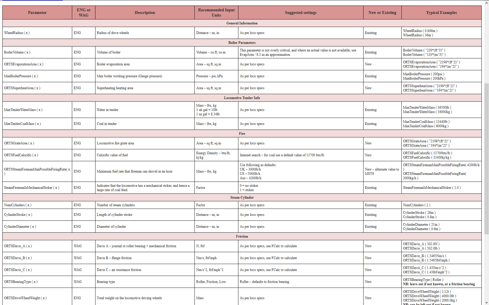
Standard Parameters for Route Building (updated Oct 2020)

top


Useful References

top